Functional details, Internal components, Usb out connector – Measurement Computing USB-PDISO8/40 User Manual
Page 13: Usb in connector, Functional details -1, Internal components -1, Usb out connector -1, Usb in connector -1
Chapter 3
Functional Details
The USB-PDISO8/40 provides SPDT relay control and isolated inputs in a plug-and-play package. All I/O
connections are made to a 40-pin connector (refer to Table 2-2 on page 2-4 for the signal pin out).
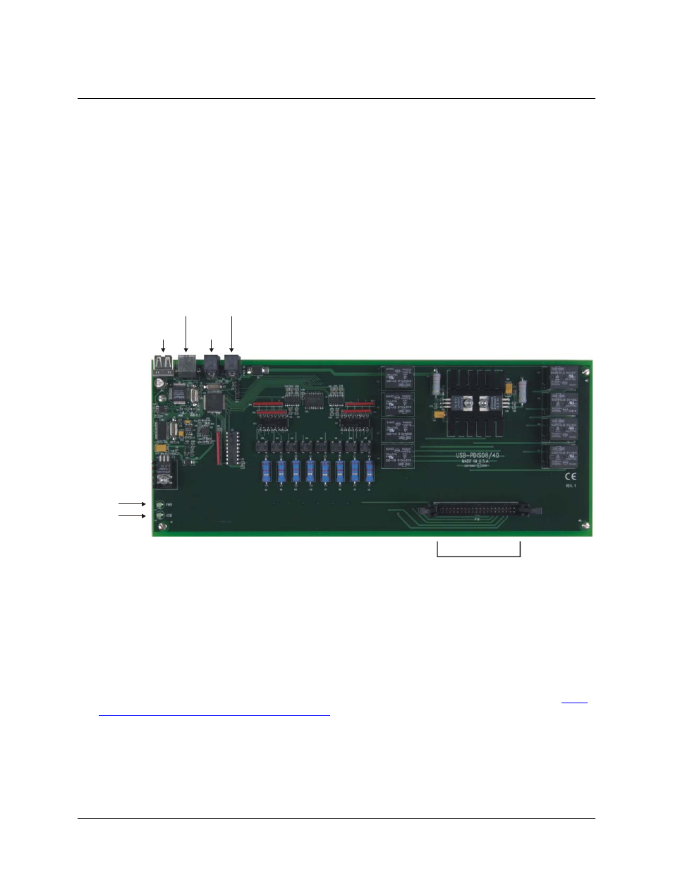
Internal components
The USB-PDISO8/40 has the following internal components, as shown in
Figure 3-1. USB-PDISO8/40 components
Two (2) USB connectors
Two (2) external power connectors
USB LED
PWR LED
40-pin I/O connector
PWR LED
USB LED
USB IN
POWER
OUT
POWER IN
USB
OUT
40-pin connector
USB OUT connector
The
USB OUT
connector is a downstream hub output port intended for use with other Measurement Computing
USB products only. The USB hub is self-powered, and can provide 100 mA maximum current at 5 V. The USB
out connector is labeled
USB OUT
on the enclosure and on the board.
For information on daisy chaining to other compatible Measurement Computing USB products, refer to "
chaining additional modules to the USB-PDISO8/40
USB IN connector
Connect the
USB IN
connector to the USB port on your computer (or USB hub connected to your computer).
The USB in connector is labeled
USB IN
on the enclosure and on the board.
3-1