Voltage drop, Voltage drop -4 – Measurement Computing USB-PDISO8/40 User Manual
Page 16
USB-PDISO8/40 User's Guide
Functional Details
Voltage drop
A drop in voltage occurs with each module connected in a daisy chain system. The voltage drop between the
module power supply input and the daisy chain output is 0.5 V maximum. Factor in this voltage drop when you
configure a daisy chain system to ensure that at least 6.5 VDC is provided to the last module in the chain.
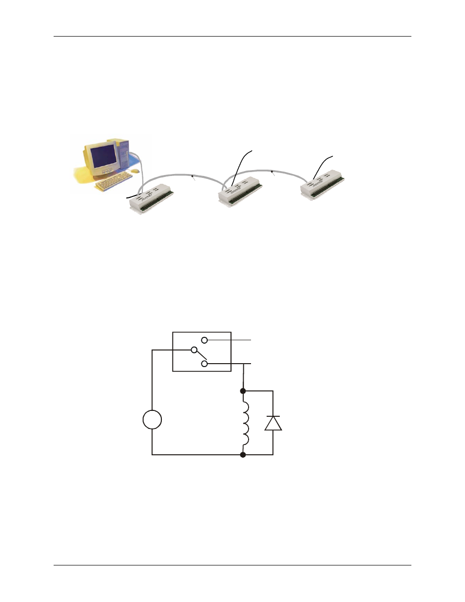
A daisy chain system in a full-power-load configuration is shown in
Figure 3-3. USB-PDISO8/40 daisy-chain connections (configuration requiring full power load)
USB port to
CB-PWR-
Relay contact protection circuit for inductive loads
When you connect an inductive load to a relay, energy stored in the inductive load can induce a large voltage
surge when you switch the relay. This voltage can severely damage the relay contacts. To limit the voltage
surge across the inductive load in a DC circuit, install a kickback diode across the inductive load. Refer to the
contact protection circuit in F
. For AC loads, install a metal oxide varistor (MOV).
Figure 3-4. Relay contact protection circuit
C
V
Inductive
Load
Kickback
Diode
NC
+
-
NO
Relay
USB IN
USB OUT
to USB IN
USB OUT
to USB IN
power supp
to
POWER IN
PWR
9
CB
-
PWR
-
9
power supply to
l
y
POWER IN
CB
-
-
power supp to
ly
POWER IN
3-4