Connecting the board for i/o operations, Connectors, cables – main i/o connector, Pin out – main i/o connector – Measurement Computing USB-PDISO8/40 User Manual
Page 11: Cabling, Connecting the board for i/o operations -4, Connectors, cables – main i/o connector -4, Pin out – main i/o connector -4, Cabling -4
USB-PDISO8/40 User's Guide
Installing the USB-PDISO8/40
Connecting the board for I/O operations
Connectors, cables – main I/O connector
Table 2-1. Board connectors, cables, accessory equipment
lists the board connectors, applicable cables, and compatible accessory boards.
Connector
P14: 40-pin ribbon connector
C40FF-x:
40
-
conductor ribbon cable, female both ends, x = length in feet.
Compatible cables
C40-37F-x: 40-pin IDC to 37-pin female D connector, x = length in feet.
Compatible accessory products
(using the C40FF-x cable)
CIO-MINI40
Compatible accessory products
(using the C40-37F-x cable)
CIO-MINI37
SCB-37
Pin out – main I/O connector
Table 2-2. 40-pin connector pin out (P14)
Signal Name
Pin
Pin
Signal Name
Input 7 terminal A
1
2
Input 7 terminal B
Input 6 terminal A
3
4
Input 6 terminal B
Input 5 terminal A
5
6
Input 5 terminal B
Input 4 terminal A
7
8
Input 4 terminal B
Input 3 terminal A
9
10
Input 3 terminal B
Input 2 terminal A
11
12
Input 2 terminal B
Input 1 terminal A
13
14
Input 1 terminal B
Input 0 terminal A
15
16
Input 0 terminal B
Relay 7 Common contact
17
18
Relay 7 Normally Open contact
Relay 6 Common contact
19
20
Relay 6 Normally Open contact
Relay 5 Common contact
21
22
Relay 5 Normally Open contact
Relay 4 Normally Closed contact
23
24
Relay 4 Common contact
Relay 4 Normally Open contact
25
26
Relay 3 Normally Closed contact
Relay 3 Common contact
27
28
Relay 3 Normally Open contact
Relay 2 Normally Closed contact
29
30
Relay 2 Common contact
Relay 2 Normally Open contact
31
32
Relay 1 Normally Closed contact
Relay 1 Common contact
33
34
Relay 1 Normally Open contact
Relay 0 Normally Closed contact
35
36
Relay 0 Common contact
Relay 0 Normally Open contact
37
38
Relay 7 Normally Closed contact
Relay 5 Normally Closed contact
39
40
Relay 6 Normally Closed contact
• •
• •
• •
• •
• •
• •
• •
• •
• •
• •
• •
• •
• •
• •
• •
• •
• •
• •
• •
• •
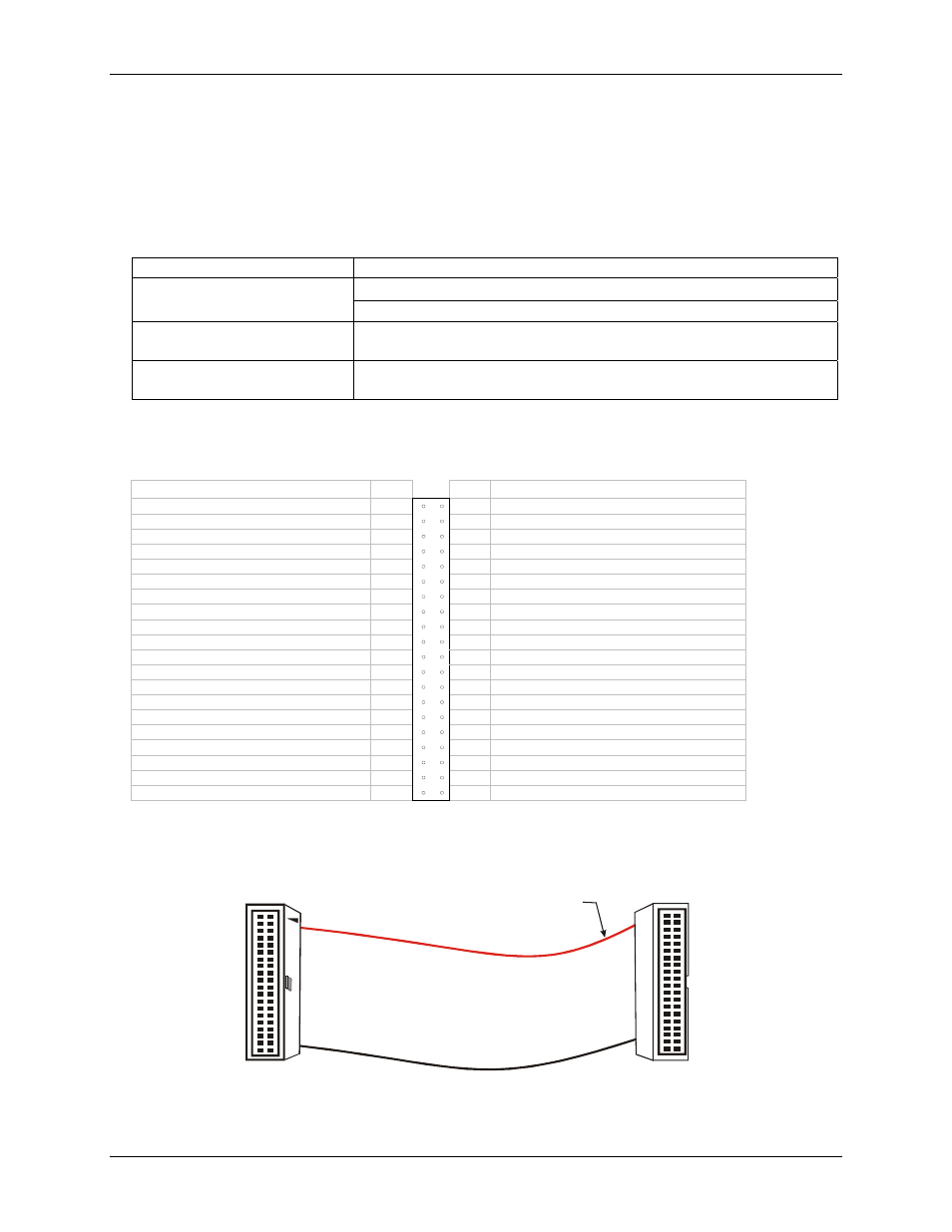
Cabling
For signal connections and termination, you can use the CIO-MINI40 screw terminal board and C40FF-x cable.
The red stripe
identifies pin # 1
40-pin Female
IDC Connector
1
2
39
40
40-pin Female
IDC Connector
1
2
39
40
Figure 2-1. C40FF-x cable
2-4