Thermocouple mode, Excitation protection – Measurement Computing USB-2404-UI User Manual
Page 15
USB-2404-UI User's Guide
Functional Details
15
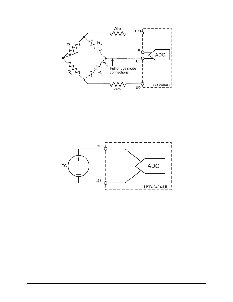
Figure 12. Half-bridge and full-bridge mode connections
Thermocouple mode
In thermocouple mode, connect the positive end of the thermocouple to HI, and the negative end of the
thermocouple to LO. This mode uses the ±1.25 mV range of the ADC to return a voltage reading. Use shielded
cables and twisted pair wiring, and ground the shielded cables.
Each channel has a built-in thermistor for cold-junction compensation (CJC) calculations. For improved CJC
sensor accuracy, operate the USB-2404-UI in a stable temperature environment, and avoid placing heat sources
near the device or its connectors. Open thermocouple detection is not supported. Refer to the Specifications
chapter for more information about accuracy. Thermocouple mode connections are shown in Figure 13.
Figure 13. Thermocouple mode connections
Excitation protection
The USB-2404-UI excitation circuit is protected from overcurrent and overvoltage fault conditions. The circuit
is automatically disabled in the event of a fault condition. Whenever possible, channels automatically recover
after the fault is removed.