Strain relief slot, Usb connector, Connecting wires to the spring terminals – Measurement Computing USB-2404-UI User Manual
Page 11
USB-2404-UI User's Guide
Functional Details
11
Connect the positive signal of the signal source to the positive input signal terminal (
HI
).
Connect the negative signal of the signal source to the negative input signal terminal (
LO
).
Connect to the excitation terminals (
EX+
/
EX–
)-if the sensor requires a separate excitation connection.
The spring terminal assignments for each input mode are listed in the following table.
6-position spring terminal assignments per input mode
Terminal
Voltage
TC
Current
Bridge
Resistance
RTD
Full
Half
Quarter
2-wire
4-wire
4-wire
3-wire
3
—
HI
EX+
EX+
HI
EX+
EX+
4
HI
—
HI
HI
—
HI
—
5
LO
LO
EX–
EX–
LO
EX–
EX–
6
—
—
LO
LO
—
LO
LO
Refer to "USB-2404-UI circuitry" on page 13 for information about connections in each mode.
Strain relief slot
Use the strain relief slot to keep the USB cable from disconnecting from the device inadvertently. Feed a tie
wrap through the slot and secure to the USB cable when it is connected to the device.
USB connector
The USB connector provides +5 V power and communication. The voltage supplied through the USB connector
is system-dependent, and may be less than 5 V. No external power supply is required.
LED
The LED indicates the device status. When connected to a USB port, the LED blinks steadily to indicate that
the device is initialized and receiving power. Refer to the following table for the possible LED states.
LED state/device status
LED state
Device status
Not lit
The device is not connected to a USB port or hub.
Continuous single-blink
The device is operating normally.
Continuous double-blink
The device is operating normally. (Connected to a USB 1.1 port or hub.)
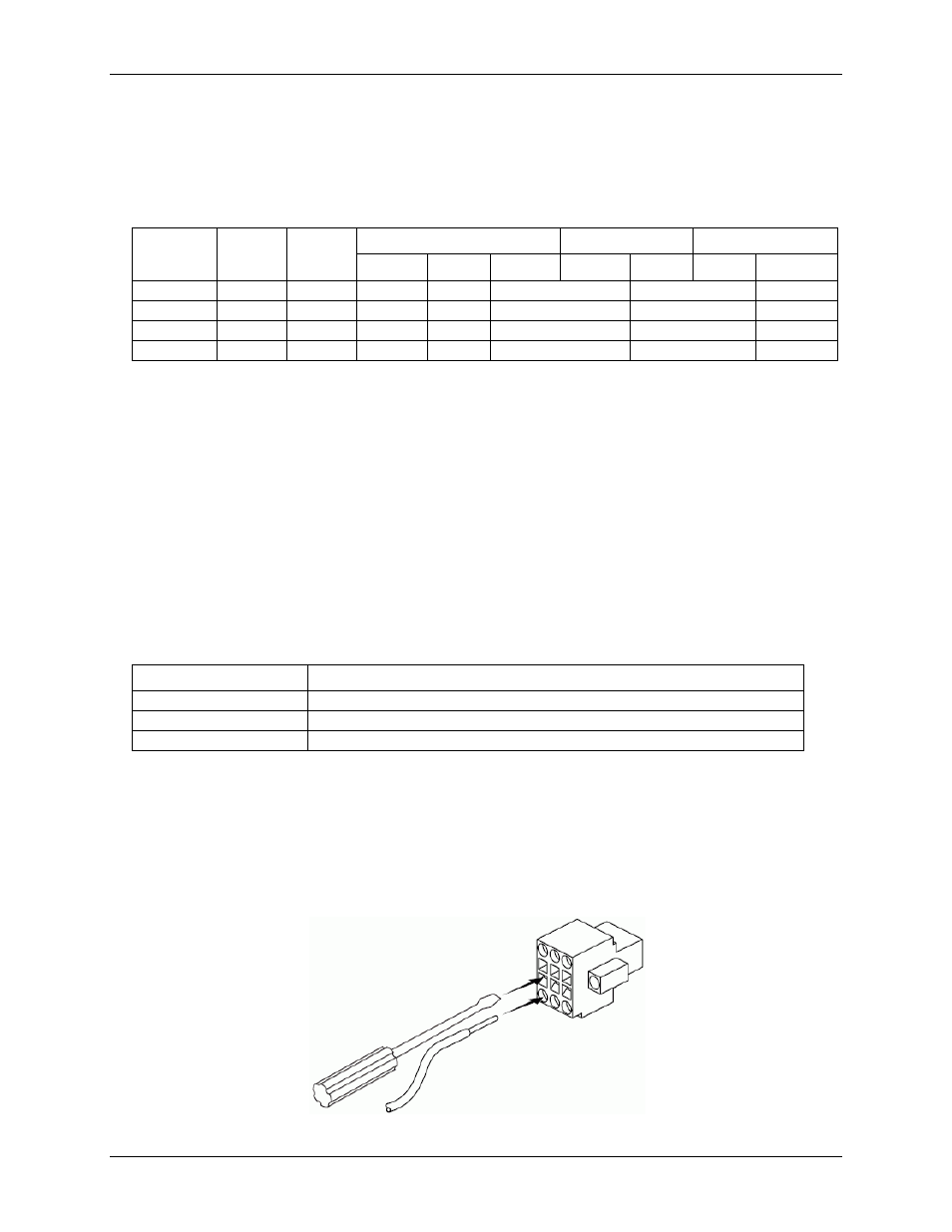
Connecting wires to the spring terminals
Use a flathead screwdriver with a blade smaller than 2.3 x 1.0 mm (0.09 x 0.04 in.) to connect wires to the
detachable spring terminal connectors. Use 18 to 28 AWG copper conductor wire with 7 mm (0.28 in.) of
insulation stripped from the end when wiring connections.
Insert the screwdriver into the spring clamp activation slot and press a wire into the corresponding connector
terminal, then remove the screwdriver to clamp the wire into the terminal.
Figure 4. Connecting a wire to the spring terminal connector