Usb-2404-ui circuitry, Analog input circuitry, Voltage and current modes – Measurement Computing USB-2404-UI User Manual
Page 13: Wire resistance and 4-wire rtd modes
USB-2404-UI User's Guide
Functional Details
13
USB-2404-UI circuitry
Analog input circuitry
The USB-2404-UI is channel-to-channel isolated. Four 24-bit analog-to-digital converters (ADCs)
simultaneously sample all four analog input channels. An excitation circuit is enabled for all input modes that
require excitation. The ADC and excitation circuits are reconfigured in each mode to accommodate each sensor
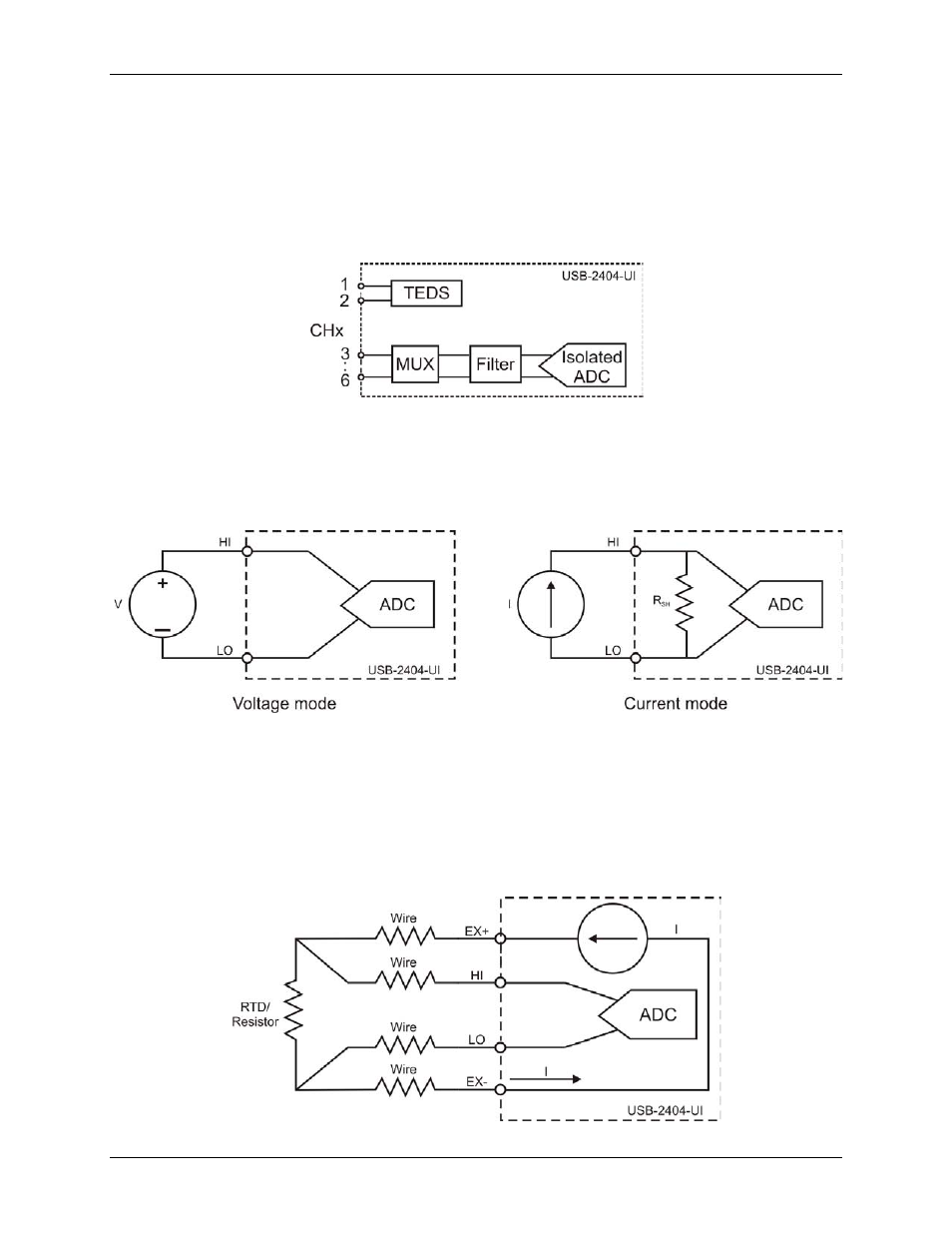
type. Figure 7 shows the input circuitry for one channel.
Figure 7. Input circuitry for one channel
Voltage and current modes
In voltage and current modes, connect the signal source to the USB-2404-UI across the HI and LO terminals.
The current is computed from the voltage that the ADC measures across an internal shunt resistor. Voltage and
current mode connections are shown in Figure 8.
Figure 8. Voltage and current mode connections
4-wire resistance and 4-wire RTD modes
4-wire resistance and 4-wire RTD modes source a current which varies based on the resistance of the load
between the EX+ and EX– terminals. The measured resistance is calculated from the resulting voltage reading.
These modes are not affected by lead wire resistance, because a negligible amount of current flows across the
HI and LO terminals due to the high impedance of the ADC. 4-wire resistance and 4-wire RTD mode
connections are shown in Figure 9.
Figure 9. 4-wire resistance and 4-wire RTD mode connections