Specifications, Analog input, Chapter 4 – Measurement Computing USB-1208FS-Plus User Manual
Page 21
21
Chapter 4
Specifications
All specifications are subject to change without notice.
Typical for 25°C unless otherwise specified.
Specifications in italic text are guaranteed by design.
Analog input
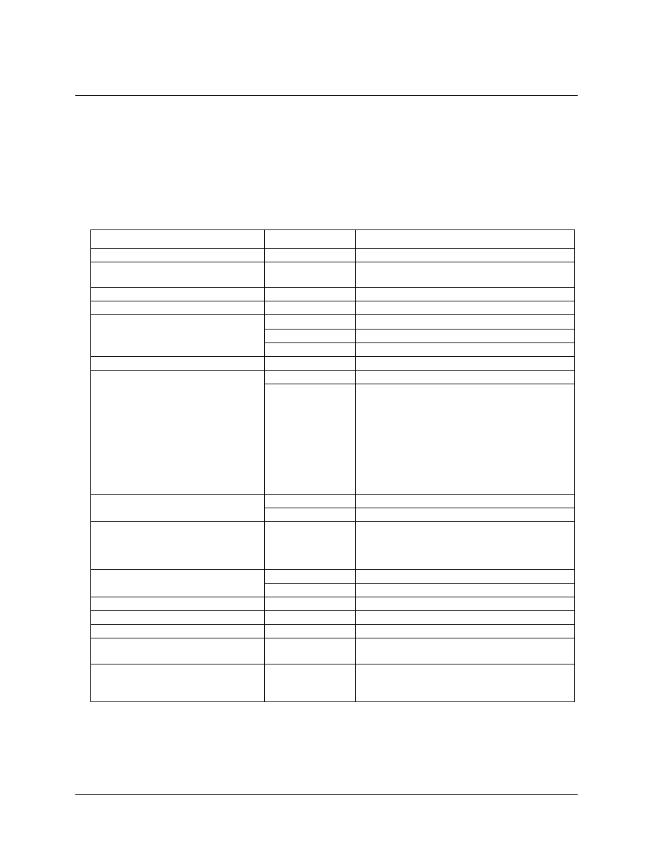
Table 1. Analog input specifications
Parameter
Condition
Specification
A/D converter type
Successive approximation type
Input voltage range for linear operation
CHx to GND
Single-ended mode: ±10 V max
Differential mode: –10 V min, +20 V max
Absolute maximum input voltage
CHx to GND
±28 V max
Input impedance
122 kΩ
Input current (Note 1)
V
in
= +10 V
70 µA typ
V
in
= 0 V
–12 µA typ
V
in
= –10 V
–94 µA typ
Number of channels
8 single-ended or 4 differential; software-selectable
Input ranges
Single-ended
±10 V,
G=2
Differential
±20 V,
G=1
±10 V,
G=2
±5 V,
G=4
±4 V,
G=5
±2.5 V, G=8
±2.0 V, G=10
±1.25 V, G=16
±1.0 V, G=20
Software-selectable
Throughput (Note 2)
Software paced
250 S/s typ, PC-dependent
Hardware paced
0.014 S/s to 50 kS/s
Channel gain queue
Software selectable. 8 elements in SE mode,
4 elements in DIFF mode.
One gain element per channel. Elements must be
unique and listed in ascending order.
Resolution (Note 3)
Differential
12 bits, no missing codes
Single-ended
11 bits
Integral linearity error
±1 LSB typ
Differential linearity error
±0.5 LSB typ
Repeatability
±1 LSB typ
Trigger source
Software-selectable
External digital: TRIG_IN
Software-selectable
Pacer source
Software-selectable
Internal
External (SYNC), rising edge triggered
Software-selectable
Note 1:
Input current is a function of applied voltage on the analog input channels. For a given input
voltage, V
in
, the input leakage is approximately equal to (8.181 * V
in
– 12) µA.
Note 2:
Maximum throughput when scanning is machine dependent.
Note 3:
The AD7870 converter only returns 11 bits (0 to 2,047 codes) in single-ended mode.