Counter input, External trigger input, Sync i/o – Measurement Computing USB-1208FS-Plus User Manual
Page 16: Power output, Ground, Accuracy
USB-1208FS-Plus User's Guide
Functional Details
16
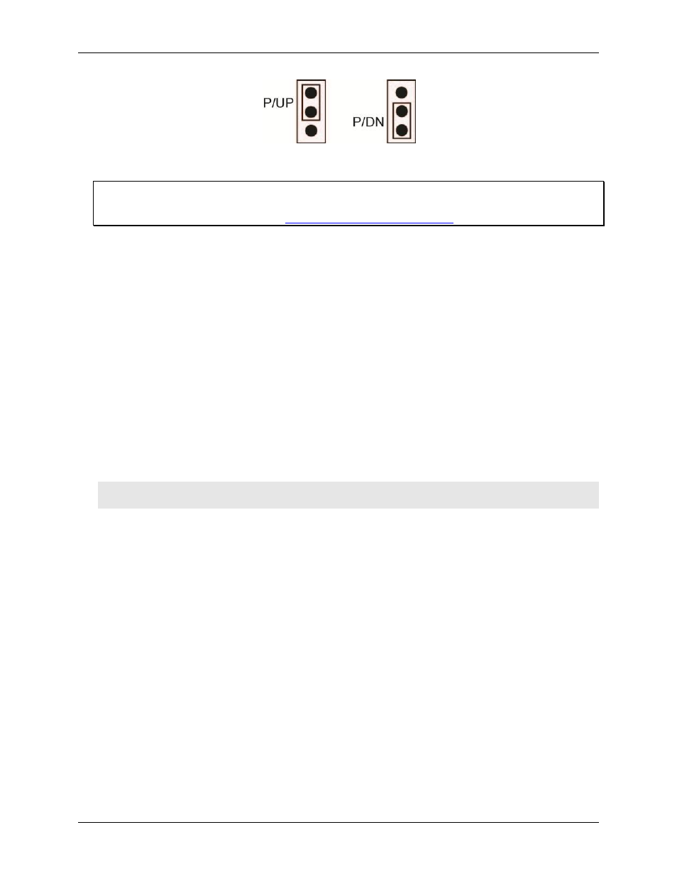
Figure 10. Pull-up/down jumper configuration
6. Replace the top section of the housing, and fasten it to the bottom section with the three screws.
For more information on digital signal connections
For more information on digital signal connections and digital I/O techniques, refer to the Guide to Signal
Connections (available on our web site
Counter input
The
CTR
connection is input to the 32-bit external event. The internal counter increments when the TTL levels
transition from low to high. The counter can count frequencies of up to 1 MHz.
External trigger input
The
TRIG_IN
connection is an external trigger input that you can configure for either rising or falling edge.
SYNC I/O
The
SYNC
terminal is a bidirectional I/O signal that can be configured as an input (default) or an output.
Configure as an external clock input to pace the A/D conversions from an external source. The SYNC
terminal supports TTL-level input signals of up to 50 kHz.
Configure as an output to pace the conversions on a second device and acquire data from 16 channels using
one clock. For more information about synchronized operations see page 19.
Power output
The
+VO
connection draws power from the USB connector on the computer.
Caution! The +VO terminal is an output. Do not connect it to an external power supply or you may damage
the device and possibly the computer.
Ground
The analog ground (
AGND
) terminals provide a common ground for all analog channels.
The digital ground (
GND
) terminals provide a common ground for the digital, trigger, counter, and sync
channels and the power terminal.
Accuracy
The overall accuracy of any instrument is limited by the error components within the system. Resolution is
often incorrectly used to quantify the performance of a measurement product. While "12-bits" or "1 part in
4,096" does indicate what can be resolved, it provides little insight into the quality of an absolute measurement.
Accuracy specifications describe the actual results that can be realized with a measurement device.
There are three types of errors which affect the accuracy of a measurement system:
offset
gain
nonlinearity
The primary error sources are offset and gain. Nonlinearity is small in each device, and is not significant as an
error source with respect to offset and gain.