Measurement Computing USB-1208FS-Plus User Manual
Page 17
USB-1208FS-Plus User's Guide
Functional Details
17
Figure 11 shows an ideal, error-free transfer function. The typical calibrated accuracy is range-dependent. Refer
to the "
" on page 22 for more information. We use a ±10 V range here as an example of
what you can expect when performing a measurement in this range.
Figure 11. Ideal ADC transfer function
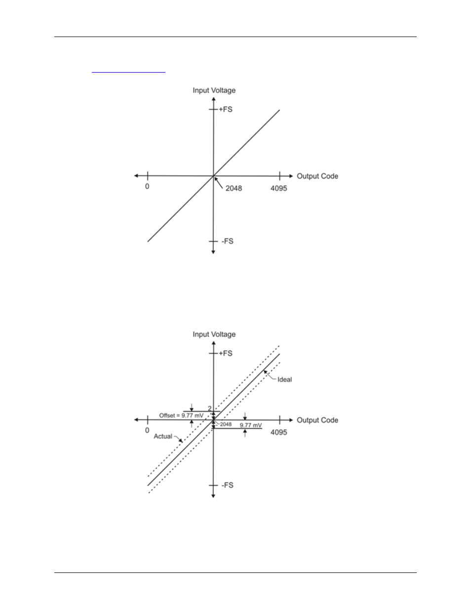
The offset error is measured at mid-scale. Ideally, a zero volt input should produce an output code of 2048. Any
deviation from this is an offset error.
Figure 12 shows an example of a transfer function with a ±9.77 mV offset error. Offset error affects all codes
equally by shifting the entire transfer function up or down along the input voltage axis.
The accuracy plots in Figure 12 are drawn for clarity and are not drawn to scale.
Figure 12. ADC transfer function with offset error