Measurement Computing USB-1208FS-Plus User Manual
Page 13
USB-1208FS-Plus User's Guide
Functional Details
13
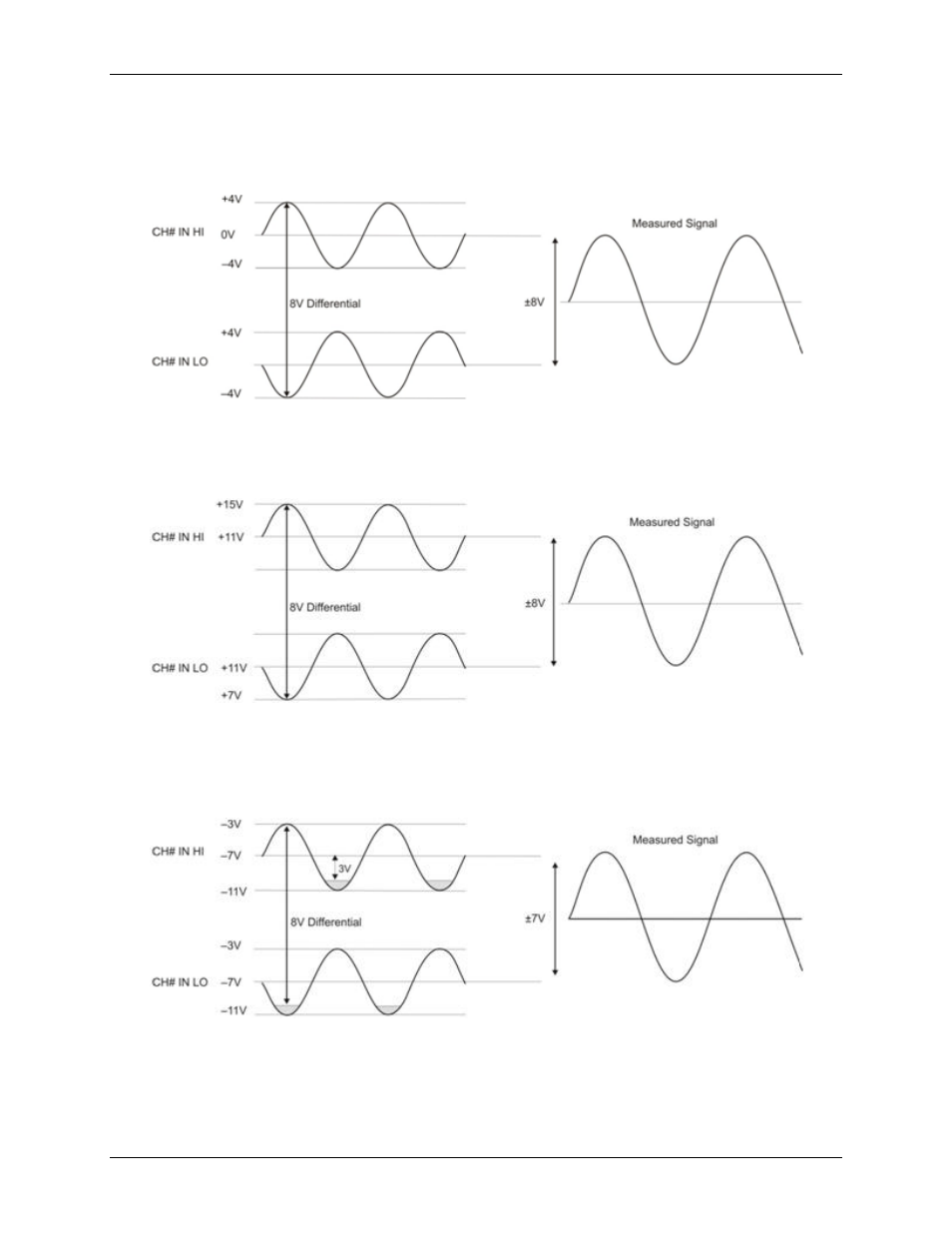
For example, you input a 4 V pp sine wave to CH# IN HI, and apply the same sine wave 180° out of phase to
CH# IN LO. The common mode voltage is 0 V. The differential input voltage swings from 4 V – (–4 V) = 8 V
to –4 V – (4 V) = –8V. Both inputs satisfy the –10 V to +20 V input range requirement, and the differential
voltage is suited for the ±10 V input range (see Figure 5).
Figure 5. Differential voltage example: common mode voltage of 0 V
If you increase the common mode voltage to 11 V, the differential remains at 8 V. Although the [common-mode
voltage + signal] on each input now has a range of +7 V to +15 V, both inputs still satisfy the –10 V to +20 V
input requirement (see Figure 6).
Figure 6. Differential voltage example: common mode voltage of 11 V
If you decrease the common-mode voltage to –7 V, the differential stays at 8 V. However, the solution now
violates the input range condition of –10 V to +20 V. The voltage on each analog input now swings from –3 V
to –11 V. Voltages between –10 V and –3 V are resolved, but those below -10 V are clipped, as shown in
Figure 7.
Figure 7. Differential voltage example: common mode voltage of
–7 V
Since the analog inputs are restricted to a −10 V to +20 V signal swing with respect to ground, all ranges except
±20V can realize a linear output for any differential signal with zero common mode voltage and full scale signal
inputs. The ±20 V range is the exception. You cannot put −20 V on CH# IN HI and 0 V on CH# IN LO, since
this violates the input range criteria.