Analog inputs, Burst mode, Analog inputs -2 – Measurement Computing PCIM-DAS16JR/16 User Manual
Page 18: Burst mode -2
PCIM-DAS16JR/16 User's Guide
Functional Details
Analog inputs
The analog input mode is switch-selectable for eight differential or 16 single-ended analog inputs. The board
offers a 100 kHz maximum sample rate in single and multi-channel scans at any gain setting. A 1024 sample
FIFO assures that data taken from the board is transferred into computer memory without the possibility of
missed samples. The board has a digital trigger input with software-selectable trigger edge.
Software selects the bipolar/unipolar input configuration and input range.
lists the analog input ranges
and resolutions for the available input configurations and gains.
Table 4-1. Input range and resolution
Bipolar Range
Resolution
Unipolar Range
Resolution
±10 V
305 µV
0 to 10 V
153 µV
±5 V
153 µV
0 to 5 V
76.3 µV
±2.5 V
76.3 µV
0 to 2.5 V
38.1 µV
±1.25 V
38.1 µV
0 to 1.25 V
19.1 µV
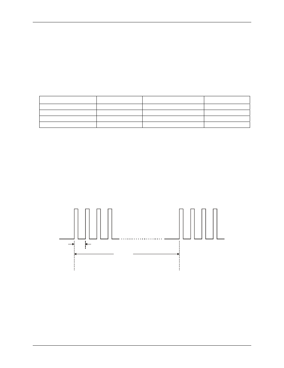
Burst mode
Channel-to-channel skew results from multiplexing the A/D inputs. Channel skew is defined as the time
between consecutive samples. For example, if four channels are sampled at a rate of 1 kHz per channel, the
channel skew is 250 µs (1 ms/4).
Burst mode minimizes channel-to-channel skew by clocking the A/D at the maximum rate between successive
channels. At the 1-ms pulse, channel 0 is sampled. After 10 µs, channel 1 is sampled. Channel 2 is sampled 10
µs after channel 1 is sampled. Channel 3 is sampled 10 µs after channel 2 is sampled. No samples are then taken
until the next 1-ms pulse, when channel 0 is sampled again. In this mode, the rate for all channels is 1 kHz, but
the channel-to-channel skew (delay) is now 10 µs. The minimum burst mode skew/delay on this board is 10 µs
(refer to
Figure 4-2. Burst mode timing
Ch0 Ch1 Ch2 Ch3
Ch0 Ch1 Ch2 Ch3
10 S
µ
Delay
Burst mode pacer is
fixed at 10 µS
The length of the delay between bursts is
set by one of the internal counters, or
may be controlled via the external trigger.
4-2