A/d trigger edge jumper, Clock frequency jumper, A/d trigger edge jumper -4 – Measurement Computing PCIM-DAS16JR/16 User Manual
Page 12: Clock frequency jumper -4
PCIM-DAS16JR/16 User's Guide
Installing the PCIM-DAS16JR/16
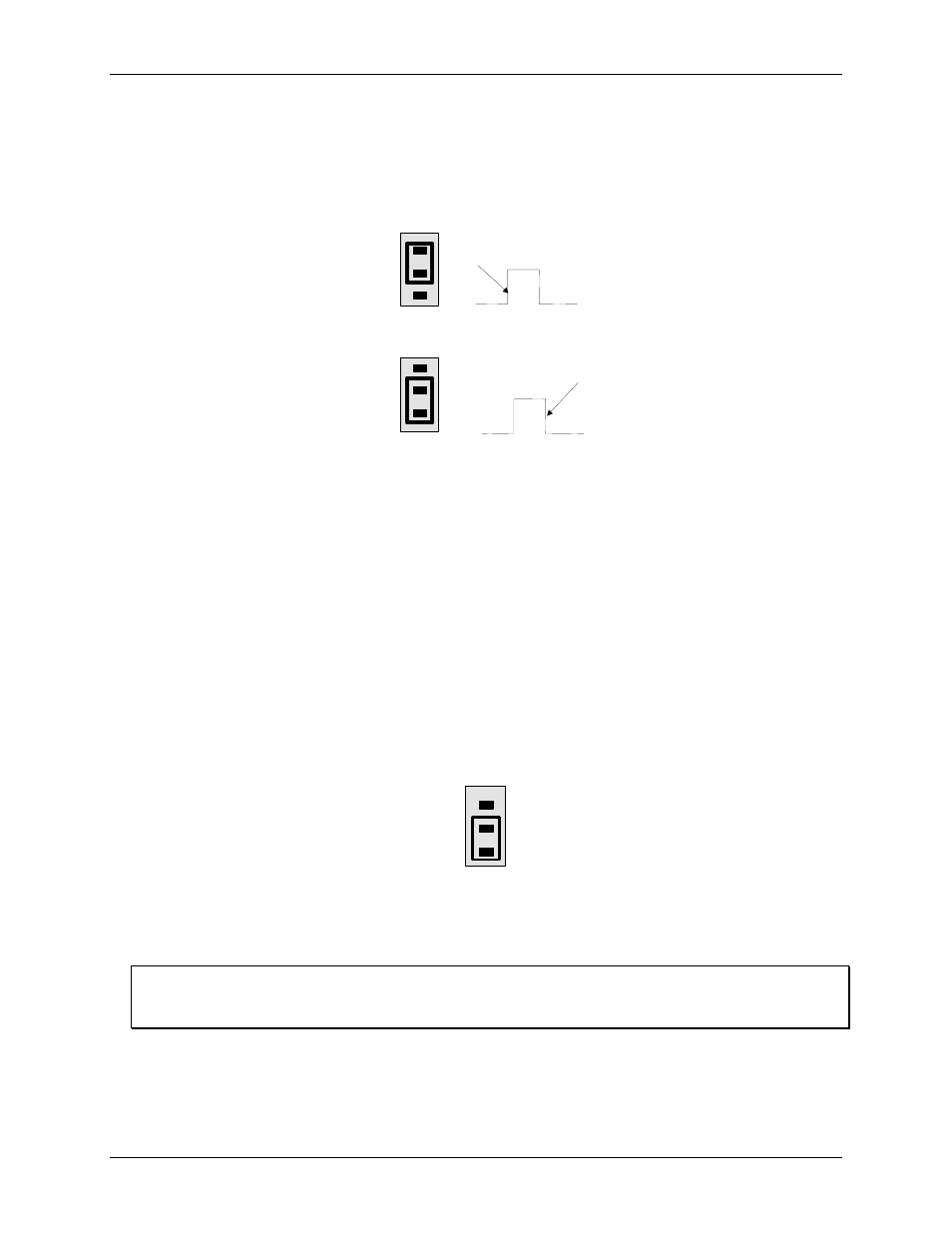
A/D trigger edge jumper
Jumper
P8
configures the edge to initiate the A/D conversion with. The options are either rising or falling edge.
The A/D trigger edge jumper is factory-configured for rising edge.
shows the jumper position for
each configuration option.
Figure 2-3. A/D trigger edge jumper
P8
Default
setting
R
F
P8
R
F
P8
Rising edge A/D trigger
DAS-16 method
Falling edge A/D trigger
DAS-16 method
For compatibility with all third-party packages, DAS-16 software, and PCIM-DAS16JR/16 software, leave this
jumper set to the default rising edge position.
If you are using the PCIM-DAS16JR/16 board in an application that is designed for compatibility with the
Keithley MetraByte DAS-1600 board, configure the trigger edge jumper for falling edge.
Clock frequency jumper
Jumper
P2
configures the frequency of the square wave that is used as a clock by the A/D pacer circuitry. This
pacer circuitry controls the sample timing of the A/D.
You can configure the frequency for 10 MHz or 1 MHz. The clock frequency jumper is factory-configured for 1
MHz, as shown in
Figure 2-4. Clock frequency jumper
P2
10M CLK SEL
1M
Configure this jumper for 10 MHz, unless you have reason to do otherwise.
The internal pacer output is also available at pin 20
The internal pacer output that drives the A/D converter is also available at pin 20 (CTR 3 Output) on the board's
main I/O connector (see Figure 2-5).
2-4