Optional components, Unpacking the pcim-das16jr/16, Installing the software – Measurement Computing PCIM-DAS16JR/16 User Manual
Page 10: Configuring the pcim-das16jr/16, Optional components -2, Unpacking the pcim-das16jr/16 -2, Installing the software -2, Default hardware configuration -2
PCIM-DAS16JR/16 User's Guide
Installing the PCIM-DAS16JR/16
Optional components
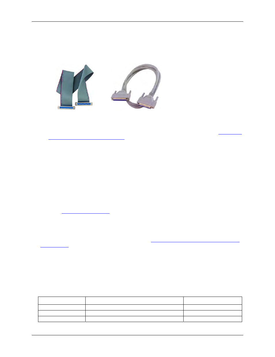
If you ordered any of the following products with your board, they should be included with your shipment.
!
Cables
C37FF-x
C37FFS-x
!
Signal termination and conditioning accessories
MCC provides signal termination products for use with the PCIM-DAS16JR/16. Refer to the "
signal termination and signal conditioning
" section on page 2-7 for a complete list of compatible accessory
products.
Unpacking the PCIM-DAS16JR/16
As with any electronic device, you should take care while handling to avoid damage from static
electricity. Before removing the PCIM-DAS1602/16 from its packaging, ground yourself using a wrist strap or
by simply touching the computer chassis or other grounded object to eliminate any stored static charge.
If any components are missing or damaged, notify Measurement Computing Corporation immediately by
phone, fax, or e-mail:
!
Phone: 508-946-5100 and follow the instructions for reaching Tech Support.
!
Fax: 508-946-9500 to the attention of Tech Support
!
Email:
Installing the software
Refer to the Quick Start Guide for instructions on installing the software on the Measurement Computing Data
Acquisition Software CD. This booklet is available in PDF
Configuring the PCIM-DAS16JR/16
The PCIM-DAS16JR/16 board has one switch and two jumpers mounted on it. Before installing the PCIM-
DAS16JR/16 in the computer, verify that the board is configured with the settings that you want. Factory
default settings are listed in T
Table 2-1. Switch/jumper factory-configured defaults
Board label
Switch/jumper description
Default setting
S1
Channel mode switch
8 channel (diff)
P8
A/D Trigger edge jumper
Rising edge
P2
Clock frequency jumper
1 MHz
The locations of each switch and jumper are shown in
2-2