Ttl to solid state relays – Measurement Computing PCI-DUAL-AC5 User Manual
Page 16
PCI-DUAL-AC5 User's Guide
Functional Details
16
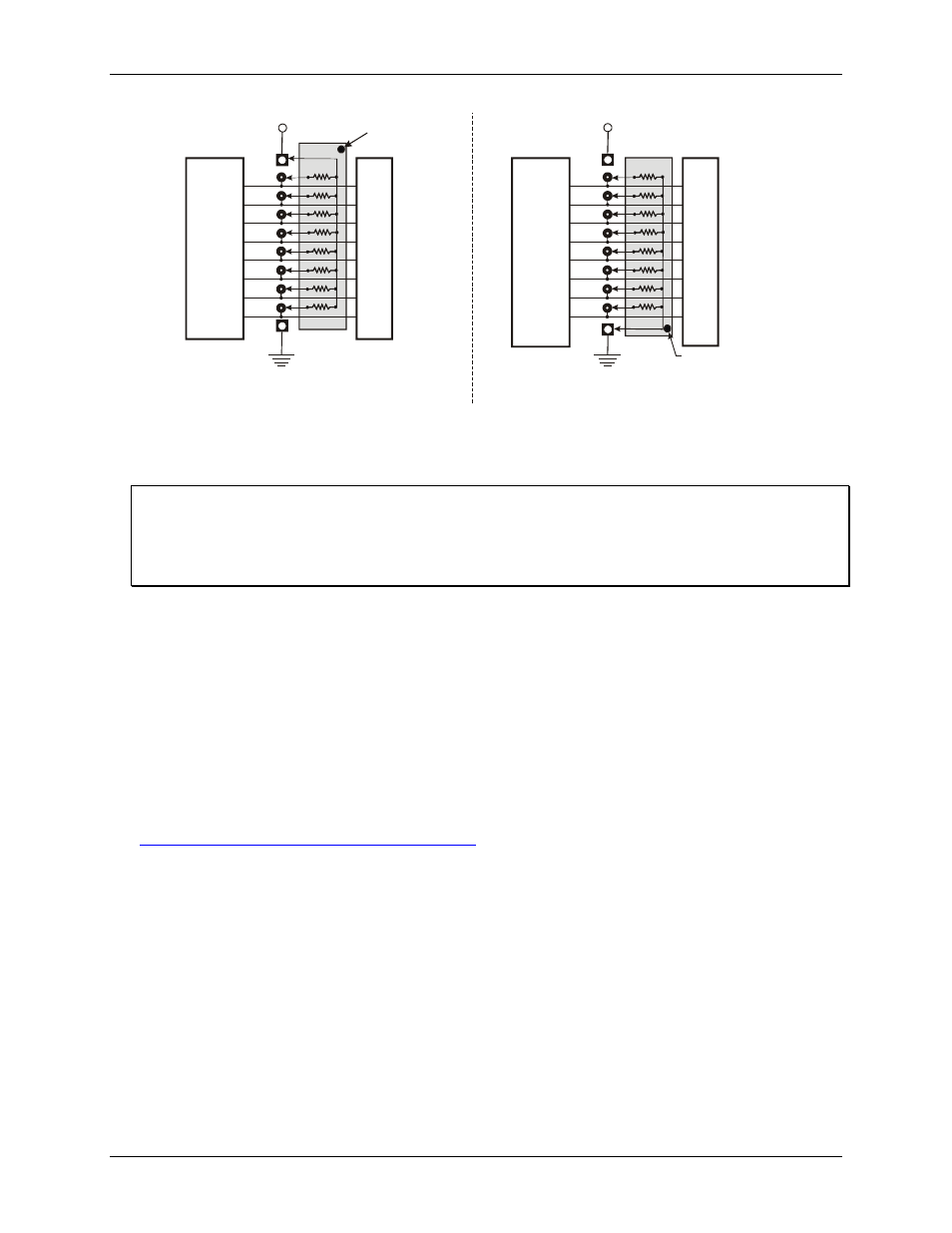
2.2 K SIP installed for pull-up
2.2 K SIP
Dot indicates the
common line
+5 VDC
HI
LO
(GND)
n7
U
s
e
r
C
o
n
n
e
c
to
r
D
ig
it
a
l
I/
O
L
in
e
s
n5
n4
n3
n2
n1
n0
n6
COM
Digital
I/O Port
n = A, B, or C
+5 VDC
2.2 K SIP installed for pull-down
2.2 K SIP
Dot indicates the
common line
HI
LO
(GND)
n7
U
s
e
r
C
o
n
n
e
c
to
r
D
ig
it
a
l
I/
O
L
in
e
s
n5
n4
n3
n2
n1
n0
n6
COM
Digital
I/O Port
n = A, B, or C
Figure 5. Pull-up and pull-down resistor SIP schematic
We recommend using 2.2 K ohm SIPs (MCC part number SP-K2.29C). Use a different value only if necessary.
Unconnected inputs float
Unconnected inputs typically float high, but not reliably. If you are using a PCI-DUAL-AC5 board for input
and have unconnected inputs, ignore the data from those lines. You do not have to terminate input lines, and
unconnected lines will not affect the performance of connected lines. Ensure that you mask out any
unconnected bits in software.
TTL to solid state relays
Many applications require digital outputs to switch AC and DC voltage motors on and off or to monitor AC and
high DC voltages. These AC and high DC voltages cannot be controlled or read directly by the TTL digital
lines of a PCI-DUAL-AC5.
Solid State Relays (SSRs) allow control and monitoring of AC and high DC voltages and provide 750 V
isolation. SSRs are the recommended method of interfacing to AC and high DC signals.
The most convenient way to use solid state relays and a PCI-DUAL-AC5 board is to purchase a solid state relay
rack. The rack recommended for use with the PCI-DUAL-AC5 board is the
SSR-PB24
from Measurement
Computing Corporation. Details on this product is available on our web site at