Pull-up and pull-down resistors – Measurement Computing PCI-DUAL-AC5 User Manual
Page 15
PCI-DUAL-AC5 User's Guide
Functional Details
15
Pull-up and pull-down resistors
TTL inputs usually, but not reliably, float high. The direction they float is dependent on the characteristics of
the circuit and is unpredictable. This means that if devices such as solid state relays, are driven by digital I/O
pins, they can be switched on whenever the computer is powered-on or is reset. To prevent unwanted
switching at power-on or reset, force all digital I/O pins to a known state by pulling all pins either high or low
through a 2.2 K ohm resistor tied to either 5V or GND.
The pull-up resistor pulls the input to a high state (+5V) when the board is in input mode, as it would be on
power-up or reset. A 2.2 K ohm resistor draws only 2 mA. A grounded 2.2 K ohm pull-down resistor pulls the
I/O line low when the board is in input mode.
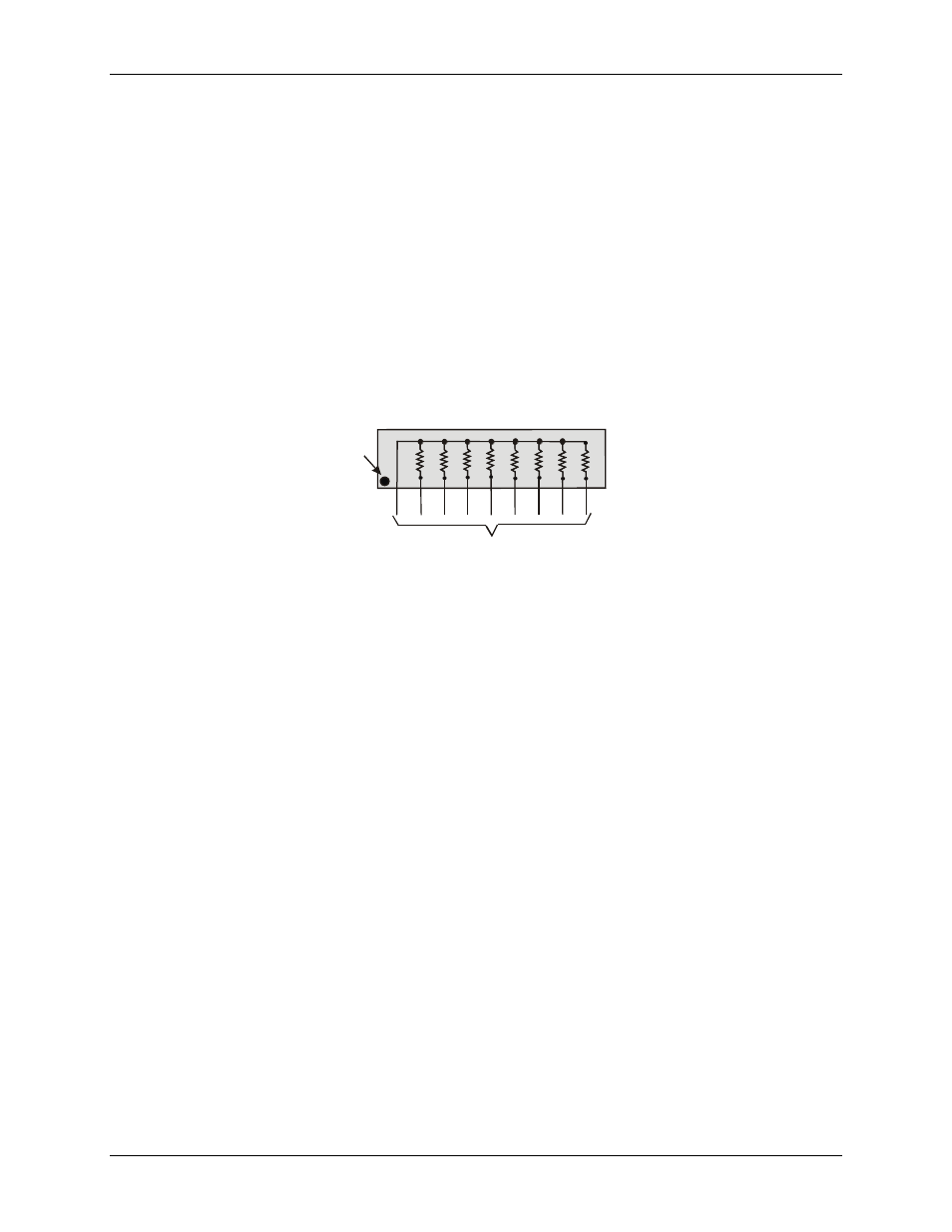
The SIP is made up of eight 2.2 K ohm resistors. One side of each resistor is connected to a single common
point and brought out to a pin. The common line is marked with a dot or line at one end of the SIP. The
remaining resistor ends are brought out to the other eight pins (refer to Figure 4).
2.2 KOhm SIP
Dot
(LO or HI)
I/O Lines
Figure 4. Eight-resistor SIP Schematic
The PCI-DUAL-AC5 board has open locations where you can install a 2.2 K ohm, eight-resistor single inline
package (SIP) resistor network for each port. The locations are adjacent to the I/O connector and are marked
PORT0A
,
PORT0B
, and
PORT0C
, and
PORT1A
,
PORT1B
, and
PORT1C
. PORT0n is associated with
FIRSTPORT, and PORT1n is associated with SECONDPORT.
When installed, the SIP establishes either a high or low logic level at each of the eight I/O lines on the port. At
each board location, A, B, and C, there are 10 holes in a line. The hole on one end is marked "HI" and is
connected to +5V. The other end is marked "LO" and is connected to GND. The eight holes in the middle
connect to eight lines of the port, A, B or C.
To pull-up lines, orient the SIP with the common pin (dot) toward the HI end; to pull-down, install the resistor
with the common pin in the LO end.
Figure 5 shows a schematic of an SIP installed in both the pull-up and pull-down positions.