Connecting the board for i/o operations, Connectors, cables – main i/o connector, Pinout – main i/o connector – Measurement Computing PCI-DUAL-AC5 User Manual
Page 10
PCI-DUAL-AC5 User's Guide
Installing the PCI-DUAL-AC5
10
Connecting the board for I/O operations
Connectors, cables
– main I/O connector
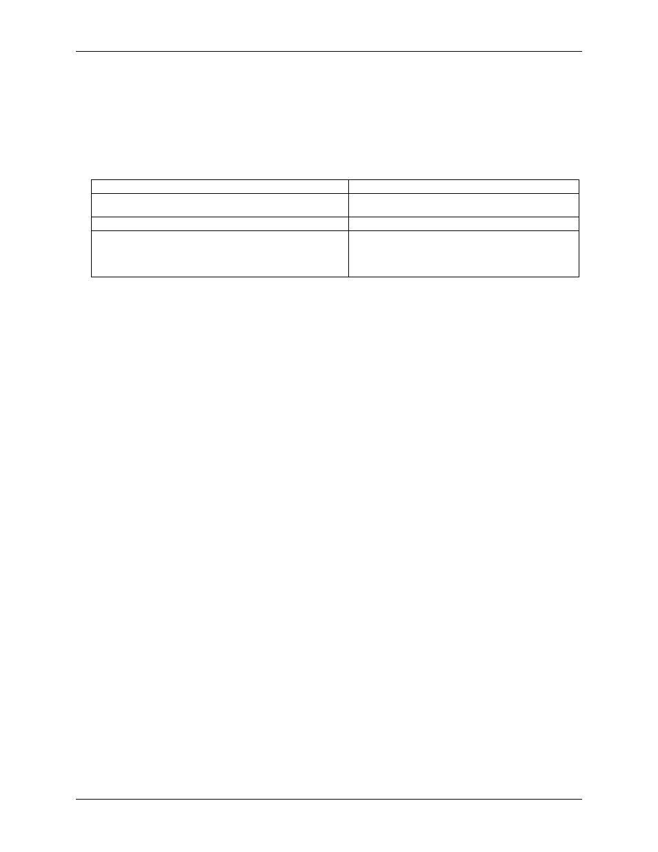
The table below lists board connectors, cables, and compatible accessory products for the PCI-DUAL-AC5.
Board connector, cables, and accessory equipment
Connector type
100-pin high-density Robinson-Nugent
Compatible cables
C100FE-x
C100FF-x
Compatible accessory product with the C100FE-x cable
SSR-PB24 (two required)
Compatible accessory products with the C100FF-x cable
CIO-MINI50 (two required)
CIO-SPADE50 (two required)
CIO-TERM100
SCB-50
The PCI-DUAL-AC5 connector is accessible through the PCI slot expansion bracket. The connector is a
standard 100-pin header connector. If you are connecting to the SSR-PB24 or equivalent, we recommend using
the C100FE-x series cable, which splits the 100-pins into two edge-connectors which you can then connect to
two SSR-PB24 racks.
If you need direct access to the digital I/O, use the C100FF-x cable to connect two CIO-MINI50s, an SCB-50
or a CIO-TERM100. These combinations bring all I/O connections out to the screw terminals.
Pinout
– main I/O connector
The I/O connector for the board is a 100-pin header connector accessible from the rear of the PC through the
expansion backplate. See Figure 1 for pin assignments.