Field wiring and signal termination – Measurement Computing PCI-DUAL-AC5 User Manual
Page 11
PCI-DUAL-AC5 User's Guide
Installing the PCI-DUAL-AC5
11
Second Port C
First Port C
First Port B
GND
A0
C7 1
GND 2
C6 3
4
5
6
7
8
9
10
11
12
13
14
15
16
17
GND 18
B6 19
20
21
22
23
24
25
26
27
28
29
30
31
32
33
34
A6 35
GND 36
A5 37
GND 38
A4 39
GND 40
A3 41
GND 42
A2 43
GND 44
A1 45
46
47
GND 48
49
GND 50
GND
C5
GND
C4
GND
C3
GND
C2
GND
C1
GND
C0
GND
B7
GND
B5
GND
B4
GND
B3
GND
B2
GND
B1
GND
B0
GND
A7
GND
GND
A0
51 C7
52
53
54
55
56
57
58
59
60
61
62
63
64
65
66
67
68
69
70
71
72
73
74
75
76
77
78
79
80
81
82
83
84
85
86
87
88
89
90 GND
91 A3
92 GND
93
94
95 A1
96
97
98
99
100 GND
GND
C6
GND
C5
GND
C4
GND
C3
GND
C2
GND
C1
GND
C0
GND
B7
GND
B6
GND
B5
GND
B4
GND
GND
B2
GND
B1
GND
B0
GND
A7
GND
A6
GND
A5
GND
A4
A2
GND
GND
0 ohm
5V
B3
0 ohm
5V.
Base + 0
Base + 2
Base + 1
Base + 4
Base + 5
Base + 6
First Port A
A A
Second Port B
Second Port A
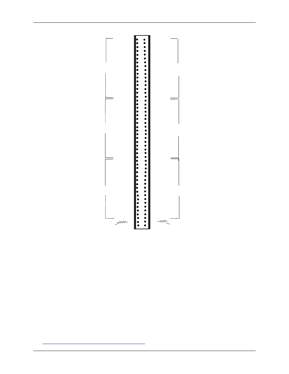
Figure 1. I/O connector pinout
The connector accepts 100-pin connectors, such as on the C100FE-2, a 2-foot cable with two edge-connectors,
or the C-100FF-2, a two-foot cable with two 50-pin header connectors.
Field wiring and signal termination
You can use the following screw terminal boards to terminate field signals and route them into the PCI-DUAL-
AC5 using the C100FF-x cable.
CIO-MINI50 – 50-pin universal screw terminal board. Two boards are required.
CIO-SPADE50 — 16" x 4" termination panel which mates with both 37-pin and 50-pin connectors. Two
boards are required.
CIO-TERM100 – 100-pin screw terminal board (daisy-chained 50-pin IDC connectors). Two boards are
required.
SCB-50 – 50 conductor, shielded signal connection/screw terminal box provides two independent 50-pin
connections.
Details on these products are available on our web site at