Pull-up and pull-down resistors – Measurement Computing PCI-DIO96H User Manual
Page 16
PCI-DIO96H User's Guide
Functional Details
16
Pull-up and pull-down resistors
The PCI-DIO96H board has open locations where you can install a 2.2 K , eight-resistor single inline package
(SIP) resistor network for each port. The locations are marked
PORT#A
,
PORT#B
and
PORT#C
(RN10 through
RN21), and are adjacent to the I/O connector. PORT0A corresponds to FIRSTPORTA, PORT1A corresponds
to SECONDPORTA, etc, as shown on the pinout diagram.
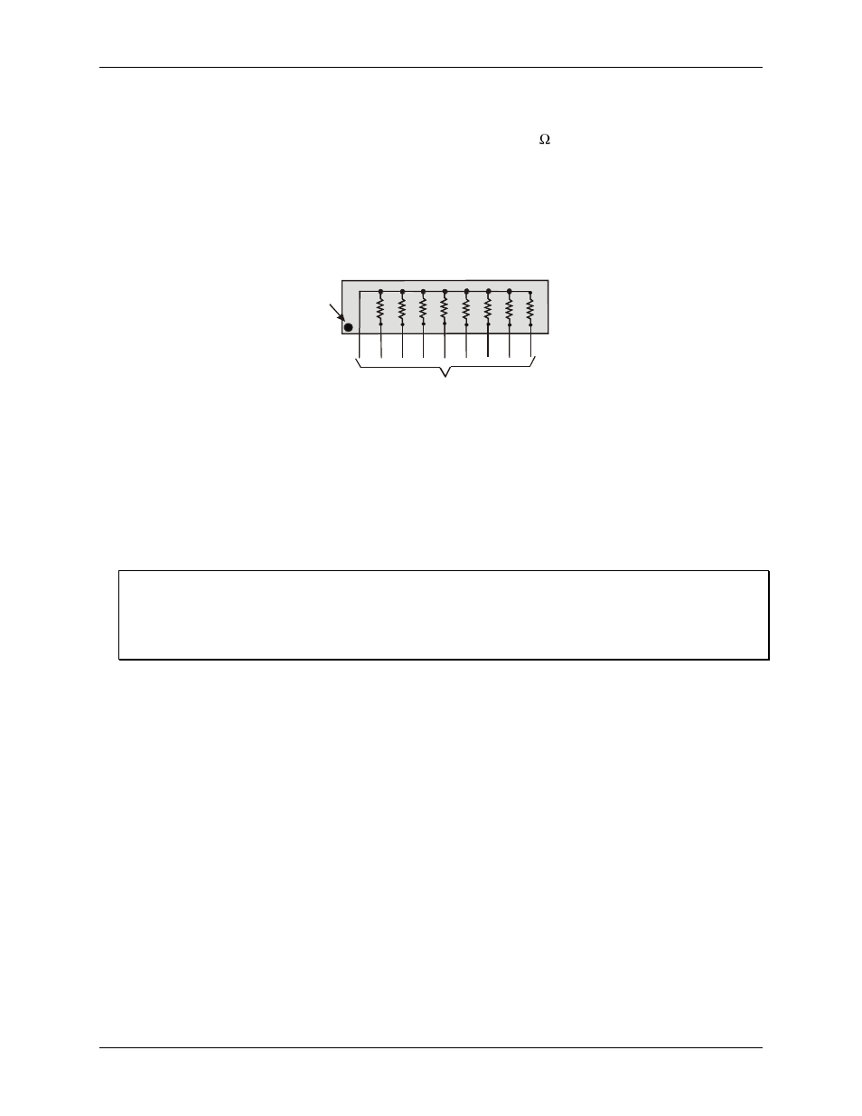
The SIP is made up of eight 2.2 K resistors. One side of each resistor is connected to a single common point and
brought out to a pin. The common line is marked with a dot or line at one end of the SIP. The remaining resistor
ends are brought out to the other eight pins (refer to Figure 4).
2.2 KOhm SIP
Dot
(LO or HI)
I/O Lines
Figure 4. Eight-Resistor SIP Schematic
The SIP may be installed as pull-up or pull-down. At each RN# location, there are 10 holes in a line. One end of
the line is +5V, the other end is GND. They are marked
HI
and
LO
respectively. The eight holes in the middle
are connected to the eight lines of a port.
For a pull-up function, mount the SIP with the common pin (marked with a dot or line) in the
HI
position.
For a pull-down function, mount the SIP with the common pin in the
LO
position.
When installing pull-up and pull-down resistor SIP packs, we recommend using a 2.2 K, eight-resistor SIP
(MCC part number SP-K2.29C).
Unconnected inputs float
Unconnected inputs typically float high, but not reliably. If you are using a PCI-DIO96H board for input and
have unconnected inputs, ignore the data from those lines. You do not have to terminate input lines, and
unconnected lines will not affect the performance of connected lines. Ensure that you mask out any
unconnected bits in software.