Functional details, Cio-erb24 and ssr-rack24 daisy chain configuration, 82c55 emulation – Measurement Computing PCI-DIO96H User Manual
Page 15
15
Chapter 3
Functional Details
CIO-ERB24 and SSR-RACK24 daisy chain configuration
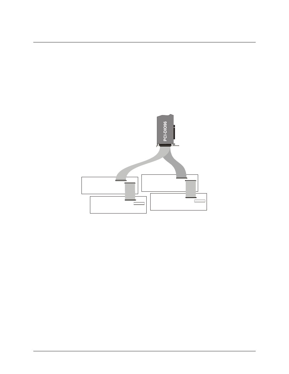
Many relay and solid-state relay (SSR) racks provide only 24-bits of digital I/O. You can configure the CIO-
ERB24 relay output board and SSR-RACK24 I/O module rack in a daisy chain configuration to use all of the
digital I/O bits provided by the PCI-DIO96H board. An example of the daisy chain configuration scheme for
each board is shown below.
The PCI-DIO96H board provides digital I/O in a group of 96 bits. Each of the C100FF-x cable's 50-pin
connectors provides 48 bits. To use all of the board's 96 digital I/O bits to control relays and/or SSRs, configure
the daisy chain as shown in Figure 3.
CIO-ERB24
or
SSR-Rack24
IN
OUT
CIO-ERB24
or
SSR-Rack24
IN
OUT
CIO-ERB24
or
SSR-Rack24
IN
OUT
CIO-ERB24
or
SSR-Rack24
IN
OUT
C100FF-x Cable
Figure 3. PCI-DIO96H to C100FF-x to relay rack daisy chain cabling
The 24 digital I/O bits on pins 1-24 control the first relay board on the chain. The 24 digital I/O bits on pins 25-
50 control the second relay/SSR board on the daisy chain and so on, for up to 100 pins.
82C55 emulation
The PCI-DIO96H board emulates the 82C55 chip. The 82C55 emulation initializes all ports as inputs on power-
up and reset. A TTL input is a high impedance input. If you connect another TTL input device to the output, it
could be turned on or off every time the board is reset.
To establish a consistent TTL level at power-up, use resistors tied to either +5V (pull-up) or ground (pull-
down). There are open locations for pull-up and pull-down resistor packs on the board.
Whenever an 82C55 emulation is powered on or reset, all pins are set to high-impedance input. Based on
standard TTL functionality, these inputs will typically float high, and may have enough drive current to turn on
external devices.
Consequently, if you have output devices such as solid state relays, they may be switched on whenever the
computer is powered on or reset. To prevent unwanted switching, and to drive all outputs to a known state after
power on or reset, pull all pins either high or low through a 2.2 K resistor.