Connecting the board for i/o operations, Connectors, cables – main i/o connector – Measurement Computing PCI-DIO96H User Manual
Page 11
PCI-DIO96H User's Guide
Installing the PCI-DIO96H
11
Connecting the board for I/O operations
Connectors, cables
– main I/O connector
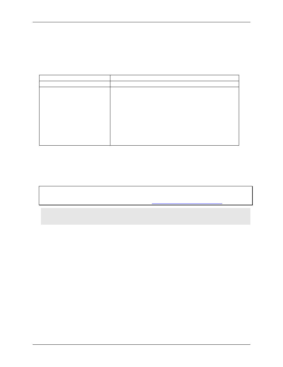
The table below lists the board connectors, applicable cables and compatible accessory boards.
Board connectors, cables, accessory equipment
Connector type
100-pin, high-density connector
Compatible cables
C100FF-x (Figure 1)
Compatible accessory products with
the C100FF-x cable
CIO-MINI50*
CIO-SPADE50*
CIO-TERM100
SCB-50
CIO-ERB24
CIO-SERB24/FD
CIO-ERB48
CIO-SERB48
SSR-RACK24
SSR-RACK48
* two devices are required
The PCI-DIO96H board has a 100-pin, high-density Robinson-Nugent male connector. Connector pinouts are
listed on page 12. The C100FF-x cable can be used to split the 100 I/O lines into two, 50-pin cables.
Board connector pins 1 to 50 are mapped directly to pins 1 to 50 on the C100FF-x cable's first 50-pin connector.
Board connector pins 51 to 100 are mapped directly to pins 1 to 50 on the C100FF-x cable's second 50-pin
connector (pin 51 is mapped to pin 1, and pin 100 is mapped to pin 50.) A sample C100FF-x cable
configuration is shown in Figure 2 on page 13.
Information on signal connections
General information regarding signal connection and configuration is available in the Guide to Signal
Connections. This document is available on our web sit
Caution! When connecting a cable to the board's I/O connector, make sure that the arrow indicating pin 1
on the board connector lines up with the arrow indicating pin 1 on the cable connector. Incorrectly
connected cables can damage the board and the I/O controller.