System throughput, Crosstalk, Analog input drift – Measurement Computing PCI-DAS6402/16 User Manual
Page 24: System throughput -3, Crosstalk -3, Analog input drift -3
PCI-DAS6402/16 User's Guide
Specifications
System throughput
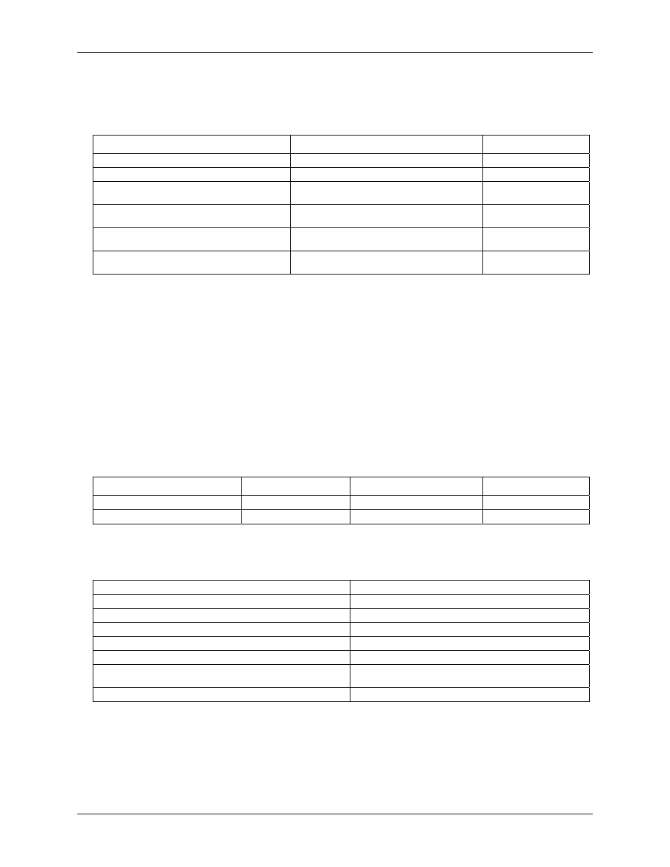
Table 4. System throughput specifications
Condition
Calibration coefficients
ADC rate (max)
1. Single channel, single input range.
Per specified range
200 kHz
2. Multiple channel, single input range
Per specified range
200 kHz
3. Single channel, multiple input ranges. All
samples in unipolar OR bipolar mode.
Default to value for cbAInScan() range
200 kHz
4. Multiple channels, multiple input ranges.
All samples in unipolar OR bipolar mode.
Default to value for cbAInScan() range
200 kHz
5. Multiple channels, multiple input ranges,
switching Unipolar/bipolar mode
Default to value for cbAInScan() range
200 kHz
6. Multiple channel, single input range,
switching Unipolar/bipolar mode.
Default to value for cbAInScan() range
200 kHz
Note 1:
For conditions 1-2 above, specified accuracy is maintained at rated throughput. Conditions 3-6
apply calibration coefficients which correspond to the range value selected in
cbAInScan()
.
These coefficients remain unchanged throughout the scan. Errors of up to 25 counts may be
incurred when switching gains while in bipolar or unipolar mode only (conditions 3 and 4).
Errors of up to 100 counts may be incurred when mixing unipolar/bipolar modes (conditions 5
and 6).
Crosstalk
Crosstalk is defined here as the influence of one channel upon another when scanning two channels at the
maximum rate. A full scale 100 Hz triangle wave is input on Channel 1; Channel 0 is tied to Analog Ground at
the 100 pin user connector. The table below summarizes the influence of Channel 1 on Channel 0 with the
effects of noise removed. The residue on Channel zero is described in LSBs.
Table 5. Crosstalk specifications
Condition
Crosstalk
Per channel rate
ADC rate
Same range to same range
3 LSB pk-pk
100 kHz
200 kHz
Any range to any range
6 LSB pk-pk
100 kHz
200 kHz
Analog input drift
Table 6. Analog input drift specifications
Analog input full-scale gain drift
0.25 LSB/°C max
Analog input zero drift
0.21 LSB/°C max
Overall analog input drift
0.46 LSB/°C max
Common mode range
±10 V
CMRR @ 60 Hz
-80 dB min
Input impedance
10 MegOhm min
Absolute maximum input voltage
!
Channel 0: ±15 V, power on or off
!
Channels 1-63: –40 V to +55 V, power on or off
Warm-up time
60 minutes
5-3