Specifications, Analog input, Specifications -1 – Measurement Computing PCI-DAS6402/16 User Manual
Page 22: Analog input -1
Chapter 5
Specifications
Typical for 25 °C unless otherwise specified.
Specifications in italic text are guaranteed by design.
Analog input
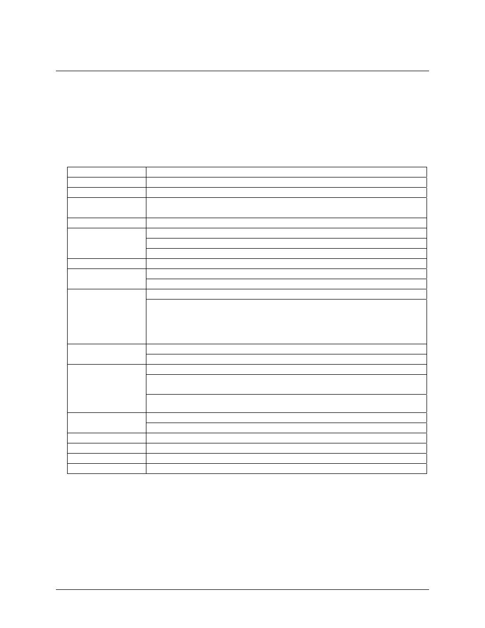
Table 1. Analog input specifications
A/D converter type
AD976A, successive approximation ADC
Resolution 16
bits
Number of channels
64 single ended; 32 differential
Input ranges (SW
programmable)
Bipolar: ±10 V, ±5 V, ±2.5 V, ±1.25 V
Unipolar: 0 to 10 V, 0 to 5 V, 0 to 2.5 V, 0 to 1.25 V
Polarity
Unipolar/Bipolar, software selectable
Internal counter – ASIC
External source (A/D external pacer)
A/D pacing (SW
programmable)
Software polled
Burst mode
Software selectable option, burst rate = 5 µS. Valid for a fixed input range only.
External digital (A/D Pacer Gate)
A/D gate sources
External analog (Analog Trigger In)
External digital: Programmable, active high or active low, level, or edge
A/D gating modes
External analog: Software-configurable for:
!
Above or below reference
!
Positive or negative hysteresis
!
In or out of window
Trigger levels set by D/A OUT 0 and/or D/A OUT 1.
External digital (A/D start trigger in and A/D stop trigger in)
A/D trigger sources
External analog (analog trigger in)
External digital: Software-configurable for rising or falling edge.
External analog: Software-configurable for positive or negative slope.
Trigger levels set by D/A OUT 0 and/or D/A OUT 1.
A/D triggering modes
Pre-/post-trigger: Unlimited number of pre-trigger samples, 16 Meg post-trigger samples.
Compatible with both digital and analog trigger options.
From 8k RAM buffer via DMA (demand or non-demand mode) using scatter gather.
Data transfer
Programmed I/O
Configuration memory
8K words
Channel/gain queue
Up to 8K elements. Programmable channel, gain, and offset.
A/D conversion time
5 µS
Calibration
Auto-calibration, calibration factors for each range stored on board in non-volatile RAM.
5-1