5 unconnected inputs – Measurement Computing PC104-DIO48 User Manual
Page 8
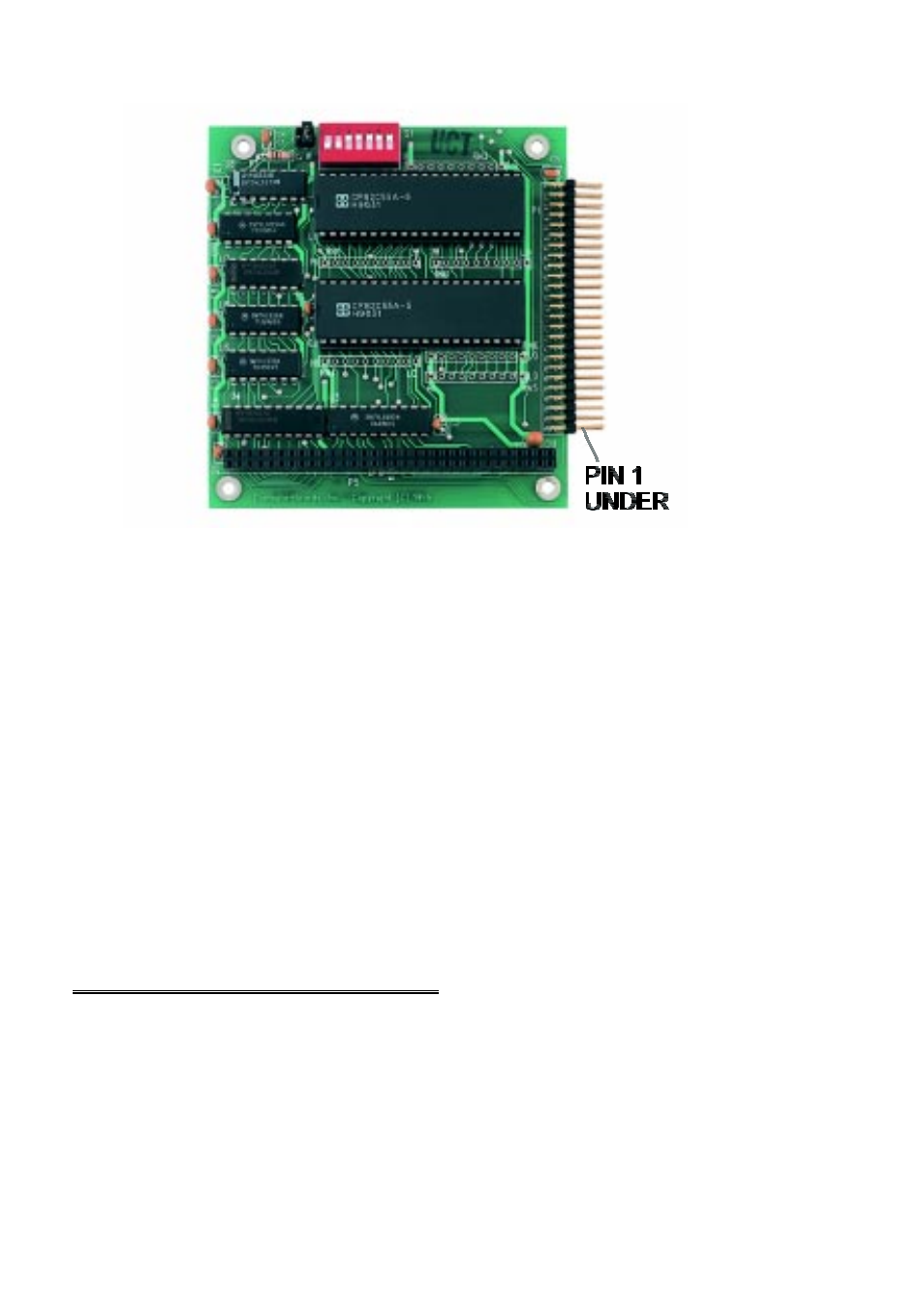
Figure 2-2. PC104-DIO48 Board Layout and Pin 1 Location
IMPORTANT NOTE: The PC104-DIO48 uses two 82C55 digital
chips for digital I/O. The 82C55 digital I/O chip initializes all ports as
inputs on power up and reset. A TTL input is a high impedance input.
If you connect another TTL input device to the 82C55 it will probably be
turned ON every time the 82C55 is reset, or, it might be turned OFF
instead. Remember, an 82C55 which is reset is in INPUT mode.
To safeguard against unwanted signal levels, all devices being controlled
by an 82C55 should be tied low (or high, as required) by a 2.2K ohm
resistor.
You will find positions for pull up and pull down resistor packs on your
PC104-DIO48 board. To implement these, please turn to the application
note on pull up/down resistors.
2.5 UNCONNECTED INPUTS
Keep in mind that unconnected inputs float. If you are using a
PC104-DIO48 board for input, and have unconnected inputs, ignore the
data from those lines.
4
- ACC-300 (7 pages)
- AI-EXP32 (20 pages)
- AI-EXP48 (19 pages)
- BTH-1208LS (30 pages)
- 6K-ERB08 (32 pages)
- BTH-1208LS Quick Start (4 pages)
- 6K-SSR-RACK08 (33 pages)
- BTH-1208LS-OEM (27 pages)
- CB-COM-Digital (68 pages)
- CB-7018 (68 pages)
- CB-7000 Utilities (44 pages)
- CB-7080D (74 pages)
- CB-COM-7033 (44 pages)
- CB-COM-7017 (72 pages)
- CB-COM-7024 (76 pages)
- CB-NAP-7000P (36 pages)
- CIO-DAC02/16 (16 pages)
- CIO-DAC02 (18 pages)
- CB-NAP-7000D (56 pages)
- CIO-DAC16-I (16 pages)
- CIO-DAC16/16 (20 pages)
- CIO-DAS08 (21 pages)
- CIO-DAC16 (20 pages)
- CIO-DAS08/JR (16 pages)
- CIO-DAS08/JR/16 (14 pages)
- CIO-DAS08/JR-AO (16 pages)
- CIO-DAS08-AOM (32 pages)
- CIO-DAS08-PGM (28 pages)
- CIO-DAS16/330 (34 pages)
- CIO-DAS48-I (17 pages)
- CIO-DAS16/M1 (38 pages)
- CIO-DAS48-PGA (18 pages)
- CIO-DAS800 (20 pages)
- CIO-DAS802/16 (22 pages)
- CIO-DAS6402/16 (40 pages)
- CIO-DAS-TEMP (20 pages)
- CIO-DDA06/16 (18 pages)
- CIO-DDA06/JR (17 pages)
- CIO-DIO24/CTR3 (21 pages)
- CIO-DIO24H (20 pages)
- CIO-DI192 (24 pages)
- CIO-DDA06 (21 pages)
- CIO-DIO48 (19 pages)
- CIO-DO192H (16 pages)
- CIO-DIO192 (20 pages)