Measurement Computing PC104-DIO48 User Manual
Page 12
Bit set/reset and bit read functions require that unwanted bits be masked
out of reads and ORed into writes.
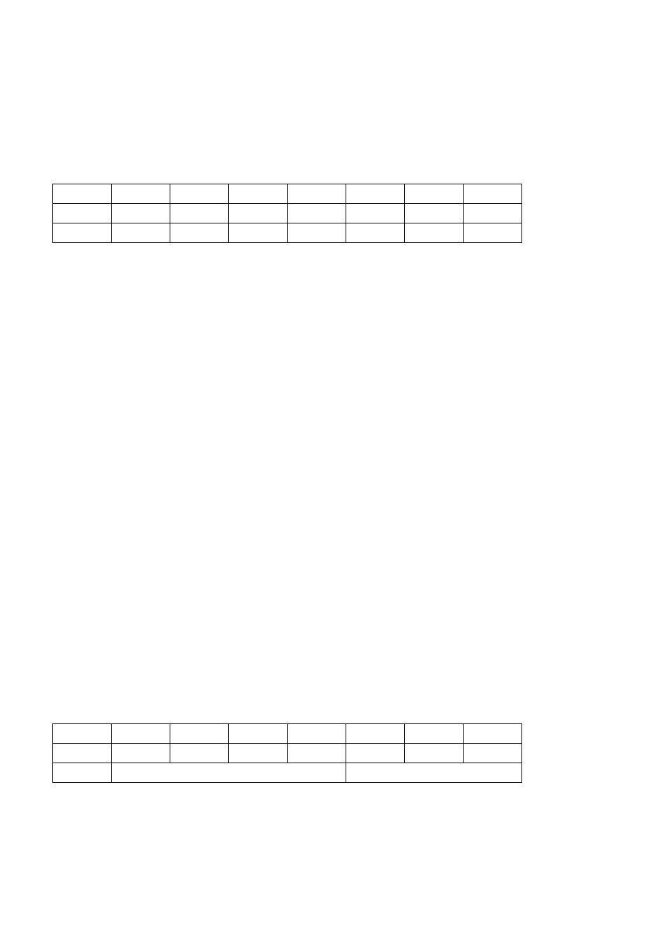
PORT C DATA
BASE ADDRESS + 2 (1st 82C55)
BASE ADDRESS + 6 (2nd 82C55)
PCL0
PCL1
PCL2
PCL3
PCH0
PCH1
PCH2
PCH3
C1
C2
C3
C4
C5
C6
C7
C8
0
1
2
3
4
5
6
7
Port C can be used as one 8-bit port of either input or output, or it can be
split into two 4-bit ports which can be independently input or output.
The notation for the upper 4-bit port is PCH3 - PCH0, and for the lower,
PCL3 - PCL0.
Although it can be split, every read and write to port C carries eight bits
of data so unwanted information must be ANDed out of reads, and
writes must be ORed with the current status of the other port.
OUTPUT PORTS
In 82C55 mode 0 configuration, ports configured for output hold the
output data written to them. This output byte may be read back by
reading a port configured for output.
INPUT PORTS
In 82C55 mode 0 configuration, ports configured for input read the state
of the input lines at the moment the read is executed, transitions are not
latched.
For information on modes 1 (strobed I/O) and 2 (bi-directional strobed
I/O), refer to an Intel or AMD data book, 82C55 data sheet.
82C55 CONTROL REGISTERS
BASE ADDRESS + 3 (1st 82C55)
BASE ADDRESS + 7 (2nd 82C55)
Group B
Group A
CL
B
M1
CU
A
M2
M3
MS
0
1
2
3
4
5
6
7
8