Measurement Computing PC104-DIO48 User Manual
Page 6
The actual address is constructed by calculating the HEX or decimal
number Base Address Select Switches which corresponds to the base
address bits the PC104-DIO48 will respond to. For example, in Figure
2-1, switches 1 and 2 down, all others are up. Switch 1 = 200 hex (512
decimal) and switch 2
= 100 hex (256 decimal). When added together
they equal 300 hex (768 decimal).
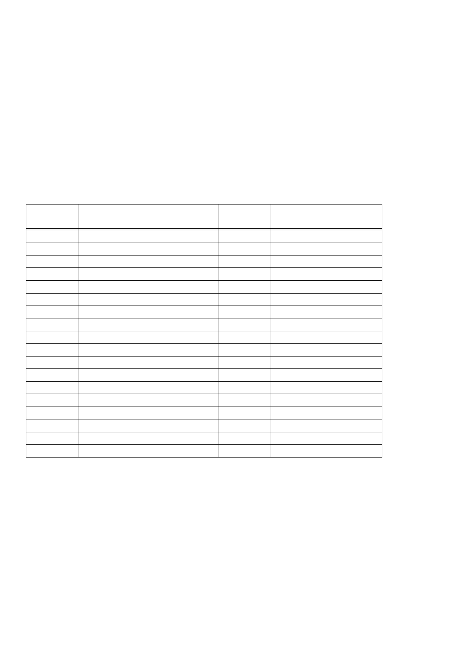
Certain address are reserved for use by the PC (Table 2-1). Others are
free and can be used by the PC104-DIO48 and other expansion boards.
We recommend that BASE = 300 hex (768 decimal) be tried first. See
Figure 2-2 for the orientation of the switch block.
Table 2-1. PC I/O Addresses
SERIAL PORT
3F8-3FF
EGA
2B0-2BF
FLOPPY DISK
3F0-3F7
PARALLEL PRINTER
270-27F
SERIAL PORT
3E8-3EF
ALT BUS MOUSE
23C-23F
CGA
3D0-3DF
BUS MOUSE
238-23B
EGA
3C0-3CF
EXPANSION UNIT (XT)
210-21F
PARALLEL PRINTER
3BC-3BF
GAME CONTROL
200-20F
MDA
3B0-3BB
HARD DISK (AT)
1F0-1FF
SDLC
3A0-3AF
80287 NUMERIC CO-P (AT)
0F0-0FF
SDLC
380-38F
8237 #2 (AT)
0C0-0DF
PARALLEL PRINTER
378-37F
NMI MASK (XT)
0A0-0AF
HARD DISK (XT)
320-32F
8259 PIC #2 (AT)
0A0-0A1
PROTOTYPE CARD
310-31F
DMA PAGE REGISTERS
080-08F
PROTOTYPE CARD
300-30F
CMOS RAM & NMI MASK (AT)
070-071
SERIAL PORT
2F8-2FF
8742 CONTROLLER (AT)
060-064
SERIAL PORT
2E8-2EF
8255 PPI (XT)
060-063
GPIB (AT)
2E0-2E7
8253 TIMER
040-043
EGA
2D0-2DF
8259 PIC #1
020-021
EGA
2C0-2CF
8237 DMA #1
000-00F
FUNCTION
HEX
RANGE
FUNCTION
HEX
RANGE
The PC104-DIO48 BASE switch may be set for address in the range of
000 to 3F8 so it should not be hard to find a free address area for your
PC104-DIO48. Once again, if you are not using IBM prototyping cards
or some other board which occupies these addresses, then 300-31Fh are
free to use. Addresses not specifically listed, such as 390-39Fh, are free.
2