1 digital i/o registers – Measurement Computing PC104-DIO48 User Manual
Page 11
The method of programming required to set/read bits from bytes is
beyond the scope of this manual. It is covered in most Introduction To
Programming books.
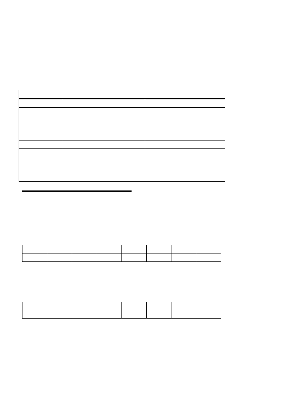
Board registers and their function are listed on the following table. Each
register has eight bits which may be one byte of data or they may be
eight individual read/write functions.
Table 3-2. Board I/O Addresses
Configure 2nd 82C55
None. No read back on
82C55
BASE + 7
Port C Output
Port C Input
BASE + 6
Port B Output
Port B Input
BASE + 5
Port A Output (2nd 8255)
Port A Input of 2nd 82C55
BASE + 4
Configure 1st 82C55
None. No read back on
82C55
BASE + 3
Port C Output
Port C Input
BASE + 2
Port B Output
Port B Input
BASE + 1
Port A Output (1st 8255)
Port A Input of 1st 82C55
BASE + 0
WRITE FUNCTION
READ FUNCTION
ADDRESS
3.1 DIGITAL I/O REGISTERS
PORT A DATA
BASE ADDRESS + 0 (1st 82C55)
BASE ADDRESS + 4 (2nd 82C55)
A0
A1
A2
A3
A4
A5
A6
A7
0
1
2
3
4
5
6
7
PORT B DATA
BASE ADDRESS + 1 (1st 82C55)
BASE ADDRESS + 5 (2nd 82C55)
B0
B1
B2
B3
B4
B5
B6
B7
0
1
2
3
4
5
6
7
Ports A & B may be programmed as input or output. Each is written to
and read from in bytes, although for control and monitoring purposes,
individual bits are typically used.
7