Measurement Computing PC104-DAS08 User Manual
Page 9
1.2 .3 RANGE SWITCH SETTING
The DIP switch labeled S2 controls the range (gain) settings for both bipolar ranges
(±5V and ±10V), and for the unipolar range (0 to 10V). For location, see Figure 1-1.
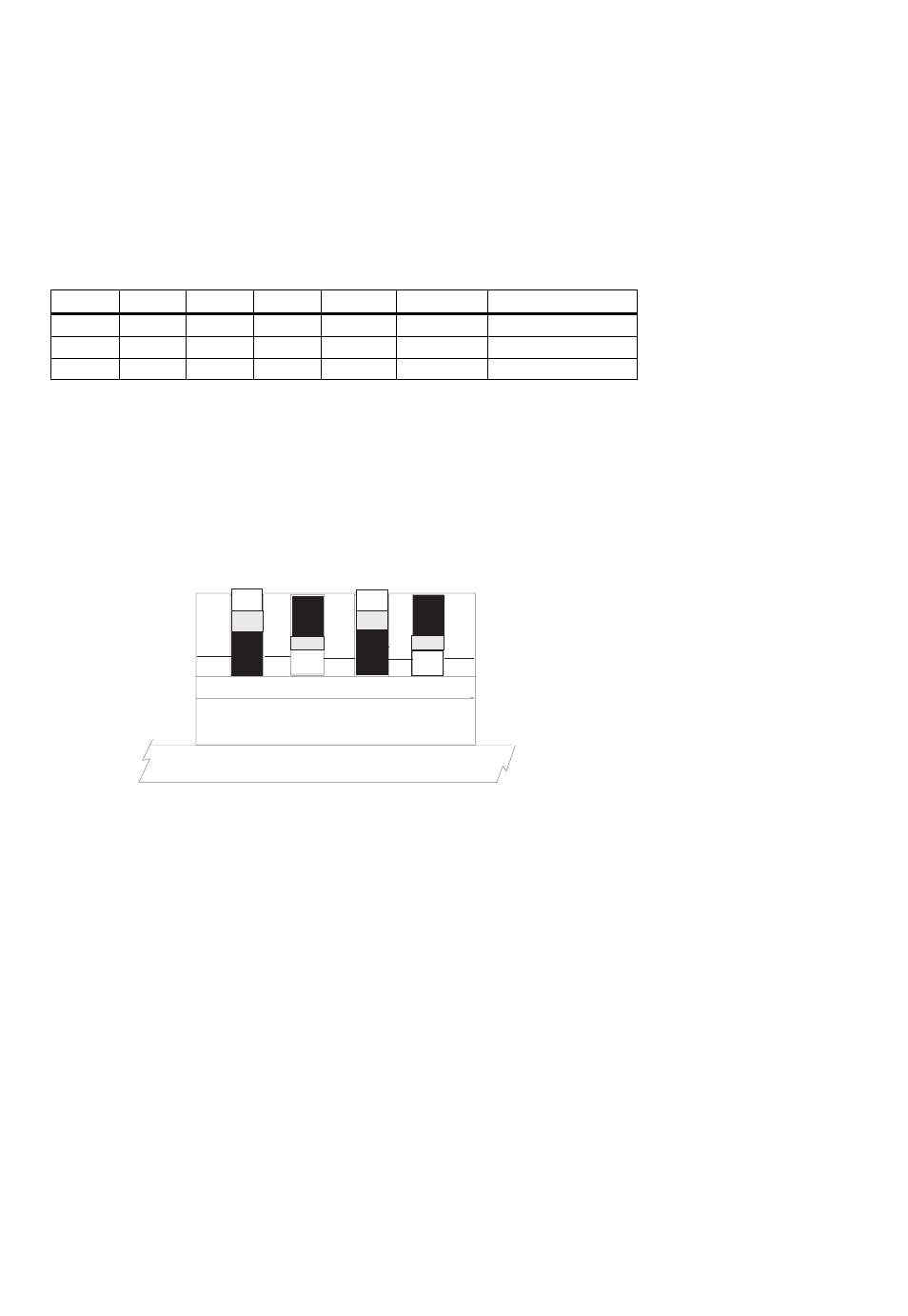
Switch S2 has four ganged switches to select an input range for the analog inputs
(Figure 1-4).
Refer to Table 1-3 to determine the correct positions of switches S2-1 through S2-4
for the range you desire.
These switches control the analog input range for all eight channels.
Table 1-3. Range Select Switch (S2) Settings
2.44mV / bit
0 to 10V
1
Up
Down
Down
Up
4.88mV / bit
±10V
0.5
Down
Up
Up
Down
2.44mV / bit
±5V
1
Down
Up
Down
Up
RESOLUTION
RANGE
GAIN
S4
S3
S2
S1
NOTE: Up = open; Down = closed.
Positions other than those listed are not valid.
The PC104-DAS08 is ready to test. You can try running the software supplied with
your board now, or you can continue reading the next section on Software
Installation
and
Calibration
.
Figure 1-4. Range Select Switch S2
5
2
1
3
4
(Up)
(Up)
(Down)
(Down)
S2 SWITCH SETTINGS FOR +/-5V
- ACC-300 (7 pages)
- AI-EXP32 (20 pages)
- AI-EXP48 (19 pages)
- BTH-1208LS (30 pages)
- 6K-ERB08 (32 pages)
- BTH-1208LS Quick Start (4 pages)
- 6K-SSR-RACK08 (33 pages)
- BTH-1208LS-OEM (27 pages)
- CB-COM-Digital (68 pages)
- CB-7018 (68 pages)
- CB-7000 Utilities (44 pages)
- CB-7080D (74 pages)
- CB-COM-7033 (44 pages)
- CB-COM-7017 (72 pages)
- CB-COM-7024 (76 pages)
- CB-NAP-7000P (36 pages)
- CIO-DAC02/16 (16 pages)
- CIO-DAC02 (18 pages)
- CB-NAP-7000D (56 pages)
- CIO-DAC16-I (16 pages)
- CIO-DAC16/16 (20 pages)
- CIO-DAS08 (21 pages)
- CIO-DAC16 (20 pages)
- CIO-DAS08/JR (16 pages)
- CIO-DAS08/JR/16 (14 pages)
- CIO-DAS08/JR-AO (16 pages)
- CIO-DAS08-AOM (32 pages)
- CIO-DAS08-PGM (28 pages)
- CIO-DAS16/330 (34 pages)
- CIO-DAS48-I (17 pages)
- CIO-DAS16/M1 (38 pages)
- CIO-DAS48-PGA (18 pages)
- CIO-DAS800 (20 pages)
- CIO-DAS802/16 (22 pages)
- CIO-DAS6402/16 (40 pages)
- CIO-DAS-TEMP (20 pages)
- CIO-DDA06/16 (18 pages)
- CIO-DDA06/JR (17 pages)
- CIO-DIO24/CTR3 (21 pages)
- CIO-DIO24H (20 pages)
- CIO-DI192 (24 pages)
- CIO-DDA06 (21 pages)
- CIO-DIO48 (19 pages)
- CIO-DO192H (16 pages)
- CIO-DIO192 (20 pages)