2 signal connections 2.1 connector diagrams – Measurement Computing PC104-DAS08 User Manual
Page 10
2 SIGNAL CONNECTIONS
2.1 CONNECTOR DIAGRAMS
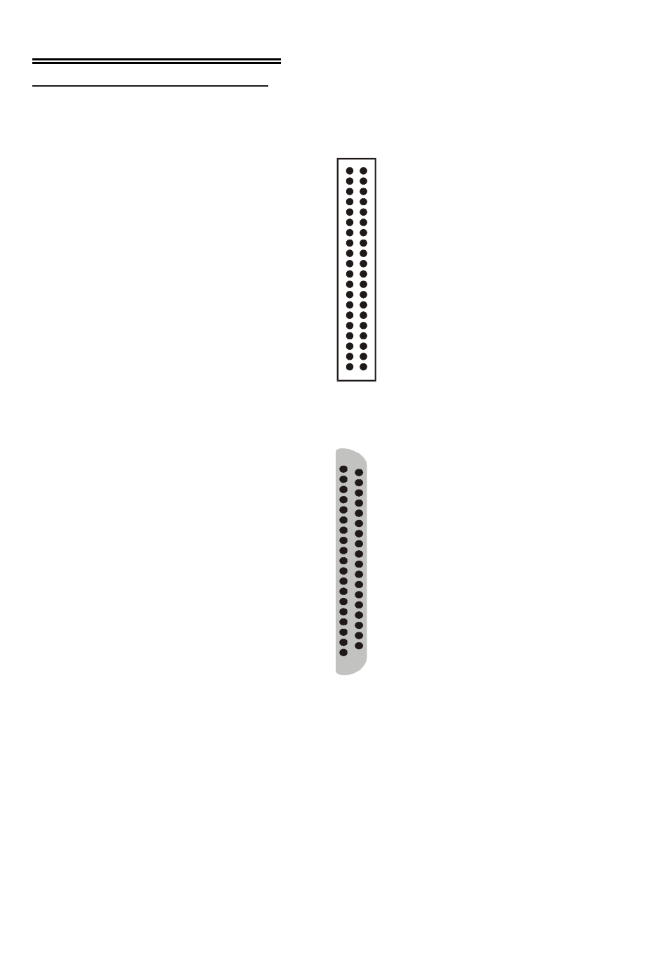
The PC104-DAS08 analog connector is a 40-pin header connector.
The connector accepts female 40-pin
header connectors, such as those on the
C40FF-2, 2 foot cable with connectors.
If connector compatibility with a
CIO-DAS08 is required, the C40-37F-#
or BP40-37 adapter cables can be used.
The C40-37F-# cable converts the
signals on the 40-pin header into the
standard DAS08 37-pin, D connector
pin assignments. If a connector on a
standard PC bracket is required, the
BP40-37 adapter cable can be used to
convert the 40-pin female header to a
37-pin male mounted on a bracket. See
Figure 2-2 for the BP40-37 pinout.
Figure 2-1. Analog Connector
Figure 2-3 shows the cabling of the
BP-40-37..
If frequent changes to signal
connections or signal conditioning is
required, please refer to the
information on the CIO-TERMINAL
and CIO-MINI37 screw terminal
boards, CIO-EXP32, 32 channels
analog MUX/AMP or the
ISO-RACK08, 8-position 5B module
interface rack.
Figure 2-2. BP40-37 Adapter Cable Pinout
6
N C 4 0
N C 3 8
C h 0 3 6
3 4
3 2
3 0
2 8
2 6
2 4
2 2
P C B u s + 5 20
G n d 1 8
In 3 1 6
In 2 1 4
In 1 / Trig 1 2
IR In pu t / X C L K 1 0
G AT E 2 8
G AT E 1 6
G AT E 0 4
P C B U S -12 V 2
C h 1
C h 2
C h 3
C h 4
C h 5
C h 6
C h 7
D ig ita l
D ig ita l
D ig ita l
D ig ita l
3 9 N C
3 7 + 1 0V R E F
3 5 LL G N D
3 3
3 1
2 9
2 7
2 5
2 3
2 1
1 9 D igita l O ut 4
1 7
O ut 3
1 5
1 3
11 C ou n ter 2 O u t
9 C o un te r 1 O ut
7 C o un te r 1 In
5 C o un te r 0 O ut
3 C o un te r 0 In
1 P C B U S + 1 2V
LL G N D
LL G N D
LL G N D
LL G N D
LL G N D
LL G N D
D igita l G nd
O ut 2
O ut 1
D ig ita l
D ig ita l
D ig ita l
3 7 C h 0 Lo w
3 6
3 5
3 4
3 3
3 2
3 1
3 0
2 9 P C B us + 5
2 8 D ig ital G n d
2 7
2 6
2 5
2 4 IR Inp u t / X C L K
2 3
2 2
2 1
2 0 P C B U S -12 V
C h 1 Lo w
C h 2 Lo w
C h 3 Lo w
C h 4 Lo w
C h 5 Lo w
C h 6 Lo w
C h 7 Lo w
D ig ita l In 3
D ig ita l In 2
D ig ita l In 1 / T rig
G ate 2
G ate 1
G ate 0
+ 10 V R E F 19
L LG N D 1 8
1 7
1 6
1 5
1 4
1 3
1 2
D igital G n d 11
D igital O u t 4 10
9
8
7
C o un te r 2 O u t 6
5
4
3
2
P C B U S + 1 2V 1
L LG N D
L LG N D
L LG N D
L LG N D
L LG N D
L LG N D
D igital O u t 3
D igital O u t 2
D igital O u t 1
C o un te r 1 O u t
C o un te r 1 In
C o un te r 0 O u t
C o un te r 0 In