Base address – Measurement Computing CIO-DIO24 User Manual
Page 9
CIO-DIO24 User's Guide
Installing the CIO-DIO24
Factory-configured default settings
Switch/jumper Descr
Default
setting
iption
Base address DIP switches
Sets the base address
300h (768 decimal)
Interrupt level jumper
pt level
terrupt level set)
Sets the interru
"X" position (no in
Wait State jumper
Enables/disables the on-board wait-state
generator.
Off (disabled)
Review the following informat
n of a s
t the base address is to let InstaCal show you the correct settings. However, if you are
already familiar with setting ISA base addresses, you may use the base address switch description below to
puter’s I/O address space. To avoid
interference with other installed boards, each board must use unique addresses. The base address is the board’s
ch
there is already a board in your
system that uses address 300 hex (768 decimal), leave the switches as they were set at the factory.
A9
200
ion to change the default configuratio
witch or jumper.
Base address
The easiest way to se
guide your base address selection.
Each I/O board uses one or more I/O address locations within your com
starting location that software writes to when communicating with the CIO-DIO24. A set of DIP switches is
used to set the base address. By placing the switch down, the CIO-DIO24 address decode logic is instructed to
respond to that address bit. A complete address is constructed by calculating the HEX or decimal number whi
corresponds to all the address bits the board has been instructed to respond to.
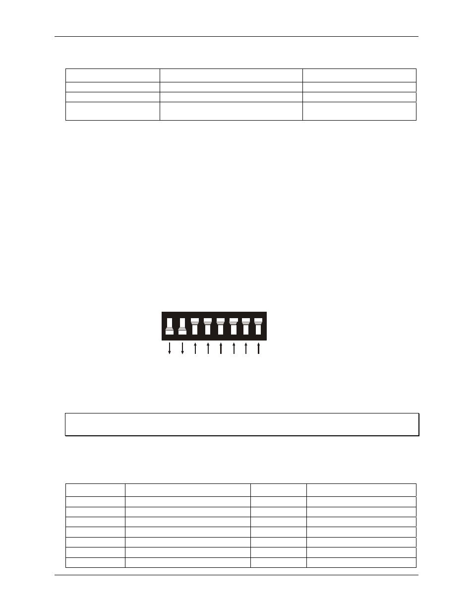
The board is shipped with the base address set to 300 hex (see Figure 2
)
. Unless
SW
HEX
A8
A7
A6
A5
A4
A3
A2
100
80
40
20
10
08
04
Figure 2. Base address switch
9
8
7
6
5
4
3
2
In the default configuration, addresses
s are up. Address 9
= 200 hex
(512 decimal), and address 8 = 100 hex (256 decimal). When added together they equal 300 hex (768 decimal).
9 and 8 are down, and all other
Disregard the numbers printed on the switch
When setting the base address, refer to the numbers printed in white on the printed circuit board.
Certain addresses are used by the computer. Other addresses are free, and may be used by the CIO-DIO24.
Refer to the following table for a list of I/O addresses.
s Summary
Hex Range
Function
Hex Range
Function
PC I/O Addres
000-00F
8237 DMA #1
2C0-2CF
EGA
020-021
8259 PIC #1
2D0-2DF
EGA
040-043
8253 TIMER
2E0-2E7
GPIB (AT)
060-063
8255 PPI (XT)
2E8-2EF
SERIAL PORT
060-064
8742 CONTROLLER (AT)
2F8-2FF
SERIAL PORT
070-071
CMOS RAM & NMI MASK (AT)
300-30F
PROTOTYPE CARD
080-08F
DMA PAGE REGISTERS
310-31F
PROTOTYPE CARD
9