Wait state, Installing the cio-dio24 – Measurement Computing CIO-DIO24 User Manual
Page 11
CIO-DIO24 User's Guide
Installing the CIO-DIO24
Hardware interrupt assignments
Name Description
Name Description
NMI
Parity
IRQ8
Real Time Clock (AT)
IRQ0
Timer
IRQ9
Re-directed to IRQ2
(AT)
IRQ1
Keyboard
IRQ10
Unassigned
IRQ2
Reserved (XT)
IRQ11
Unassigned
INT 8-15 (AT)
IRQ3
COM OR SDLC
IRQ12
Unassigned
IRQ4
COM OR SDLC
IRQ13
80287 MUNERIC CO-P
IRQ5
Hard Disk (XT)
IRQ14
Hard Disk
LPT (AT)
IRQ6
Floppy Disk
IRQ15
Not assigned
IRQ7
LPT
Wait state
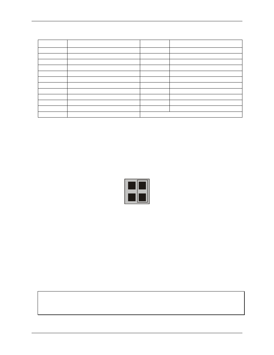
The CIO-DIO24 board has a wait state jumper which you can set to enable an on-board wait state generator
(see Figure 4). A wait state is an extra delay injected into the processor's clock via the bus. This delay slows
down the processor when the processor addresses the CIO-DIO24 board, so that signals from slow devices
(chips) will be accepted. The wait state generator is only active when the CIO-DIO24 is being accessed. Your
PC will not be slowed down in general by using the wait state.
O
N
O
F
F
WAIT
STATE
Figure 4. Wait state jumper
The jumper is shown in
is configured for
OFF
(wait state is disabled).
Because all PC expansion board busses are slowed to either 8 MHz or 10 MHz, the wait state will generally not
be required. If you experience sporadic errors from the 82C55 digital I/O chip (reset, port direction swaps), try
enabling the wait state generator.
Installing the CIO-DIO24
After you configure the base address, you can install the CIO-DIO24 into your computer. Follow the steps
below.
Install the MCC DAQ software before you install your board
The driver needed to run your board is installed with the MCC DAQ software. Therefore, you need to install
the MCC DAQ software before you install your board. Refer to the Quick Start Guide for instructions on
installing the software.
11