Cabling, Field wiring, signal termination, and conditioning, Field – Measurement Computing CIO-DIO24 User Manual
Page 13: Wiring, signal termination, and conditioning
CIO-DIO24 User's Guide
Installing the CIO-DIO24
Cabling
19
37
1
20
19
37
1
20
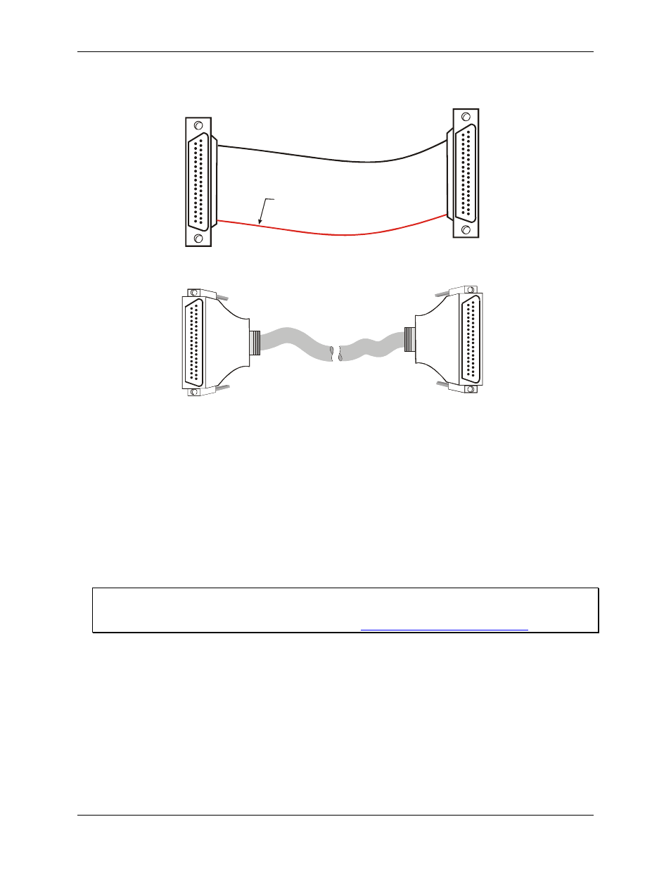
The red stripe
identifies pin # 1
Figure 6. C37FF-x cable
19
1
37
20
37
20
1
Figure 7. C37FFS-x cable
19
Field wiring, signal termination, and conditioning
tioning products with the CIO-DIO24.
You can use the following cabling, screw termination, and signal condi
13
CIO-MINI37
– 37-pin screw terminal board.
CIO-SPADE50 – 16" X 4" termination panel which mates with both 37-pin and 50-pin connectors.
CIO-MINI50 – 50-pin screw terminal board.
gnal conditioning.
SSR-RACK48 – 48-channel, solid-state relay mounting rack with quad-format modules.
CIO-ERB24 – 24 Form C relays, 6 Amp relay accessory board for digital signal conditioning.
CIO-ERB48 – 48 Form C relays, 6 Amp, relay, 50-pin accessory board for digital signal conditioning.
General information regarding signal connection and configuration is available in the Guide to Signal
Connections
. This document is available on our web site at
www.mccdaq.com/signals/signals.pdf
.