Functional details, Signal level control – Measurement Computing CIO-DIO24 User Manual
Page 14
Chapter 3
Functional Details
All of the digital outputs and inputs are CMOS TTL (Transistor-Transistor Logic). TTL is an industry term that
describes a standard for digital signals which are either at 0 V or 5 V (nominal).
The voltages and currents associated with external devices range from less than a hundred mA at a few volts for
lamps etc., to 50 Amps at 220 volts for electric heaters or other high-load equipment. Attempting to connect
such loads directly to the CIO-DIO24 will damage the I/O chip. Heavy loads such as these require external
relays.
Digital Interfacing
In addition to load matching, digital signal sources often need to be filtered or "de-bounced". Refer to the Guide
to Signal Connections
at
for information on digital interfacing.
Signal level control
The 82C55 digital I/O chip initializes all ports as inputs on power- up and reset. A TTL input is a high
impedance input. If you connect another TTL input device to the 82C55 it could be turned ON or OFF every
time the 82C55 is reset.
To prevent unwanted signal levels, and to drive all inputs on the device you are controlling to a known state
after power up or reset, install pull-up or pull-down resistors. If you are using the board to control items that
must be OFF on reset, install pull-down resistors.
A pull-up resistor pulls all digital pins up to +5 V (high logic level). A pull-down resistor pulls all digital pins
down to 0 V (low logic level).
The CIO-DIO24 has open locations where you can install a single inline package (SIP) resistor network for
each port. When installed, the SIP establishes either a high or low logic level at each of the I/O lines on the
port.
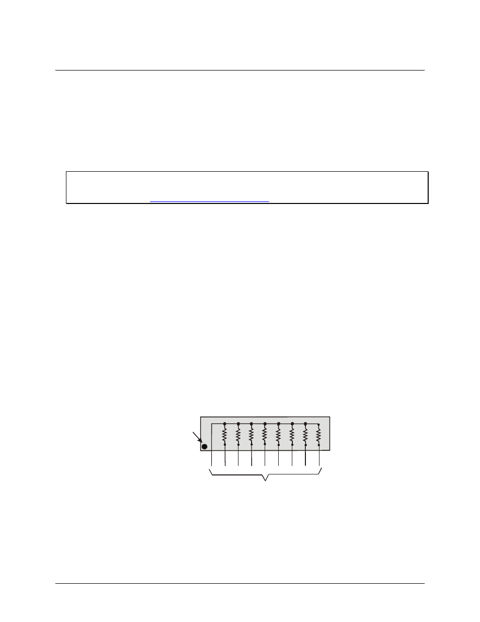
The SIP is made up of eight 2.2 KΩ resistors. One side of each resistor is connected to a single common point
and brought out to a pin. The common line is marked with a dot or line at one end of the SIP. The remaining
resistor ends are brought out to the other eight pins (see Figure 8).
2.2KOhm SIP
Dot indicates the
common line
(LO or HI)
I/O Lines
Figure 8. Eight-resistor SIP schematic
Install the SIP on the CIO-DIO24 board at the locations labeled PORT A, PORT B and PORT C. Figure 9
les
shows a schematic of an SIP installed in both the pull-up and pull-down positions. Each port prov
in a line. The end labeled
HI
connects to +5V. The end marked
LO
connects to GND. The eight holes in the
middle (n0 –n7) connect to the eight lines of the Port, A, B or C.
14