Interrupt level – Measurement Computing CIO-DIO24 User Manual
Page 10
CIO-DIO24 User's Guide
Installing the CIO-DIO24
Hex Range
Function
Function
Hex Range
0A0-0A1
8259 PIC #2 (AT)
K (XT)
320-32F
HARD DIS
0A0-0AF
T)
LLEL PRINTER
NMI MASK (X
378-37F
PARA
0C0-0DF
8237 #2 (AT)
380-38F
SDLC
0F0-0FF
80287 NUMERIC CO-P (AT)
3A0-3AF
SDLC
1F0-1FF
HARD DISK (AT)
3B0-3BB
MDA
200-20F
GAME CONTROL
3BC-3BF
PARALLEL PRINTER
210-21F
EXPANSION UNIT (XT)
3C0-3CF
EGA
238-23B
BUS MOUSE
3D0-3DF
CGA
23C-23F
ALT BUS MOUSE
3E8-3EF
SERIAL PORT
270-27F
PARALLEL PRINTER
3F0-3F7
FLOPPY DISK
2B0-2BF
EGA
3F8-3FF
SERIAL PORT
You can set the ba
ess in the range of 000-3FC. I
re not using IBM
ng cards o
ich occupies these ad
e CIO-DIO24 board's default address of
ree to use.
s not spec
such as 390-39Fh, are not
nd may
ailable. Check your
for other
O addresses.
pt leve
an input
evel on Pin 2,
IR Enable
.
er and
g table for some typical interrupt assignments on a
computer.
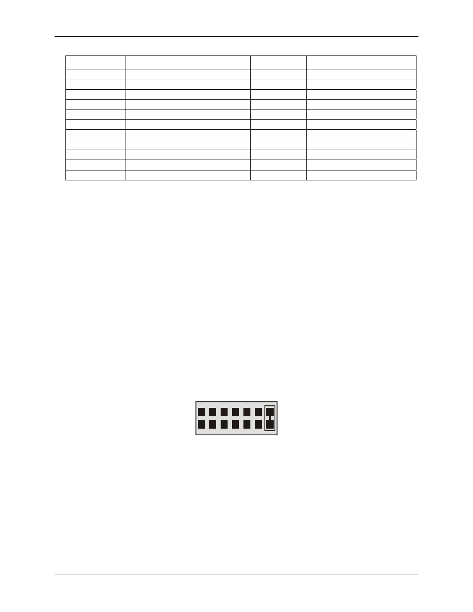
The CIO-DIO24 is shipped with the jumper in the "
X
" position, which means that no interrupt level is set
ace
se address switch to any addr
f you a
prototypi
r another board wh
dresses, th
300h is f
Addresse
ifically listed,
reserved a
be av
computer
boards which may use I/
Interru
l
The trigger logic on the CIO-DIO24 is quite simple. Pin 1 (
IR Input
) of the board's 37-pin connector is
jumper which maps the interrupt directly onto the PC bus. The signal to the bus is buffered. The buffer is
enabled by a LOW l
Interrupts are hardware-initiated software routines. Most hardware interrupts are assigned by the comput
are reserved for internal system use. Refer to the followin
(Figure 3). Leave the jumper in the default "X" position for now. If your software employs interrupt service
routines, it will direct you to select an IRQ level. Use the jumper block labeled
IR1
above the PC bus interf
(gold pins) if you want to set the interrupt.
IR1
2 3 4 5 6 7 X
Figure 3. Interrupt level select jumper (no interrupt level set)
10