Differential configuration, Channel gain queue, Analog output – Measurement Computing BTH-1208LS User Manual
Page 16: External clock input
BTH-1208LS User's Guide
Functional Details
16
Single-ended measurements using differential channels
To perform a single-ended measurement using differential channels, connect the signal to the
CHxH
input, and
ground the associated
CHxL
input.
Differential configuration
When the analog input channels are configured for differential input mode, four analog input channels are
available. A low-noise precision programmable gain amplifier (PGA) is available on differential channels. Each
analog input has 12-bit resolution and offers software-selectable analog input ranges of ±20 V, ±10 V, ±5 V,
±4V, ±2.5 V, ±2.0 V, ±1.25 V, and ±1.0 V.
In differential mode, the input signal is measured with respect to the low input, and is delivered through three
wires:
Connect the wire carrying the signal to be measured to
CHxH
.
Connect the wire carrying the reference signal to
CHxL
.
Connect the third wire to
AGND
.
In differential mode, the following two requirements must be met for linear operation:
Any analog input must remain in the
−10 V to 20 V range with respect to ground at all times.
The maximum differential voltage on any analog input pair must remain within the selected voltage range.
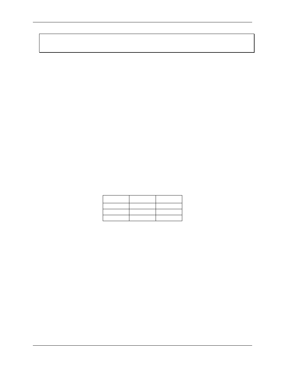
Channel gain queue
The channel gain queue feature allows you to set up a scan sequence with a unique per-channel gain setting and
channel sequence. The gain settings are stored in a channel-gain queue list that is written to local memory on
the device.
The channel-gain queue list can contain up to up to 8 elements in single-ended mode or four elements in
differential mode. The elements must be unique and listed in ascending order. An example of a three-element
list is shown in the table below.
Sample channel gain queue list
Element
Channel
Range
0
CH0
BIP10V
1
CH2
BIP5V
2
CH3
BIP10V
When a scan begins with the gain queue enabled, the BTH-1208LS reads the first element, sets the appropriate
channel number and range, and then acquires a sample. The properties of the next element are then retrieved,
and another sample is acquired. This sequence continues until all elements in the gain queue have been selected.
When the end of the channel list is detected, the sequence returns to the first element in the list. This sequence
repeats until the specified number of samples is acquired.
Carefully match the gain to the expected voltage range on the associated channel or an over range condition
may occur. Although this condition does not damage the device, it does produce a useless full-scale reading,
and can introduce a long recovery time due to saturation of the input channel.
Analog output
Two 12-bit analog outputs are available at
AOUT0
and
AOUT1
.
Each analog output channel has an output range of 0 V to 2.5 V. Throughput is system-dependent.
The D/A is software paced.
External clock input
Connect an external clock signal to
AICKI
to pace input scanning operations.