System description – MEGA Corp. MCC-OPS-1 User Manual
Page 10
MCC35-CAT735-1
5 Aug 2010
SECTION 2
System Description
2-3
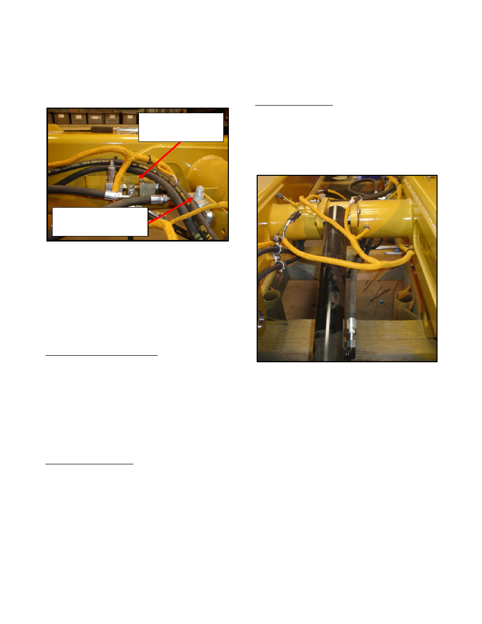
Tailgate Restraint (Stinger) Valve Assembly
The valve assembly consists of a main solenoid
control valve and a counter balance valve.
These manifolds hosed together and mounted to
the body RT main beam and cross tube
respectively. The two valve assemblies
combine to route and control hoist valve
pressure and return for the tailgate cylinder
function.
Main Solenoid Control Valve
The main solenoid control valve contains a
pressure relief and solenoid valve. The pressure
relief valve controls the clamping pressure for
the stinger to keep the tailgate door closed.
Pressure relief settings are field adjustable for
each specific type of container or load being
transported.
Counter Balance Valve
Mounted to a plate and hosed to the main
solenoid control solenoid. The valve assists in
maintaining the holding pressure for the stinger.
Pressure relief settings are field adjustable for
each specific type of container or load being
transported.
Theory of Operation
The tailgate restraint valve assembly functions
as commanded by the remote activation
switches while the vehicle is stationary or the
hoist lever while the vehicle is in motion.
Tailgate Restraint (Stinger) Cylinder
The cylinder is connected to the body assembly
cross tube at one end and the tailgate assembly
at the other end. The cylinder receives
hydraulic pressure from the tailgate restraint
valve assembly.
Main Solenoid
Control Valve
Counter Balance Valve