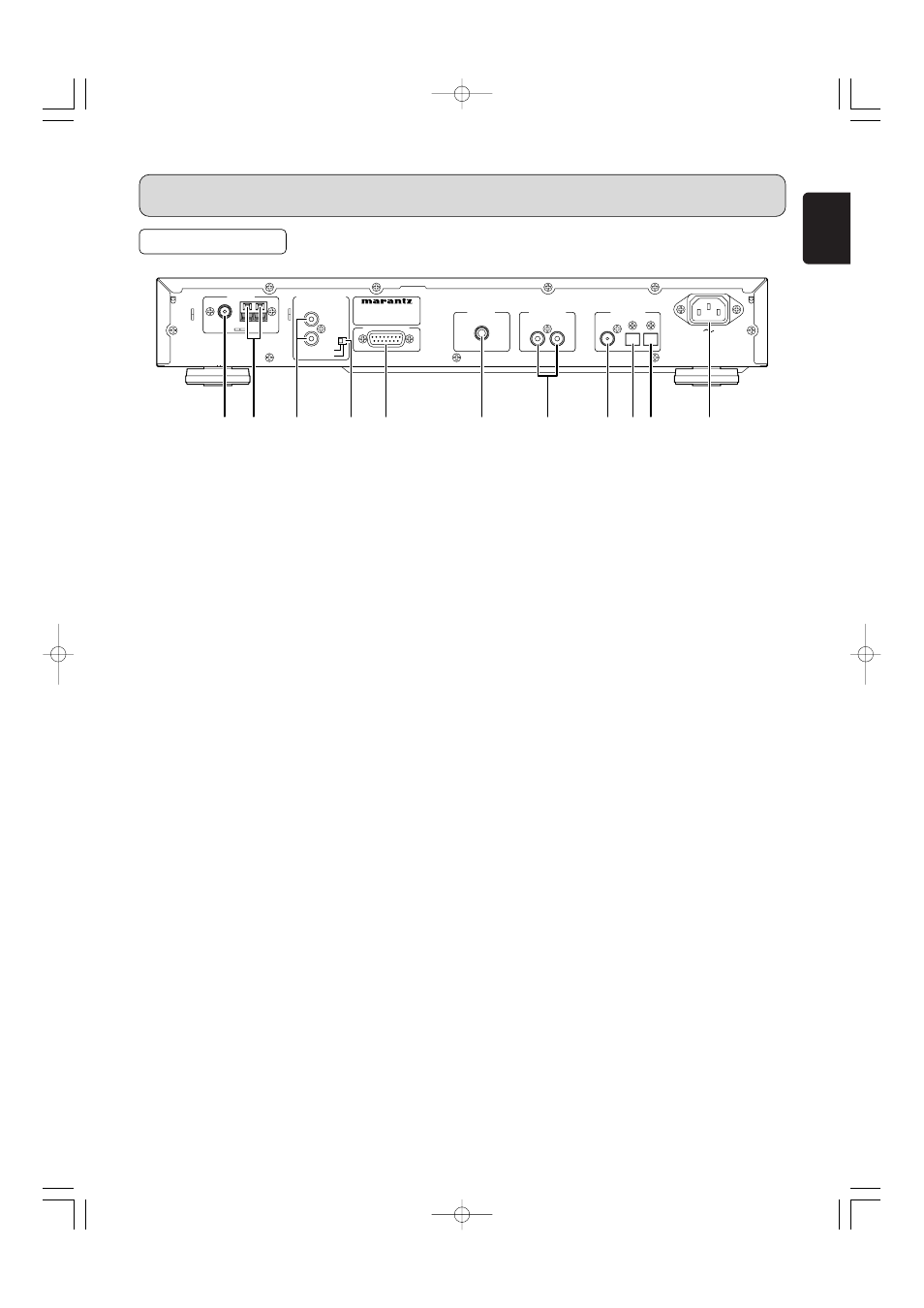
Rear panel, Part names and functions, A fm antenna terminal (75 ohms) – Marantz ST7001N User Manual
Page 9: B am antenna and ground terminals, C remote control in and out connectors, D external/internal switch, E service port, F dab antenna terminal, G analog out (analog output) connectors, J rdi out (digital optical output) connector
5
ENGLISH
PART NAMES AND FUNCTIONS
REAR PANEL
a FM antenna terminal (75 ohms)
Connect an external FM antenna with a coaxial cable, or
a cable network FM source.
b AM antenna and ground terminals
Connect the supplied AM loop antenna. Use the
terminals marked “AM” and “GND”. The supplied AM
loop antenna will provide good AM reception in most
areas. Position the loop antenna until you hear the best
reception.
c REMOTE CONTROL IN and OUT connectors
Using the supplied remote control connecting cord,
these connectors enable this unit to be connected to a
Marantz component equipped with remote control
connectors. These connections make it possible to
control an entire system that centers on the amplifier or
other such component.
d EXTERNAL/INTERNAL switch
Before the unit was shipped from the factory, this switch
was set to INTERNAL to enable the remote sensor built
into the unit to be used.
Before using the supplied connecting cord to make the
connection between the unit and the remote control
connectors on a Marantz equipment, set the switch to
EXTERNAL.
Note
• Signals cannot be received from the remote control
unit if the switch is kept at EXTERNAL when the unit is
to be used on its own.
e SERVICE PORT
This port is to be used for service purpose. Normally, it is
not used.
f DAB antenna terminal
Connect an external DAB antenna with a coaxial cable.
g ANALOG OUT (analog output) connectors
The audio signals are output from these connectors.
h DIGITAL OUT COAX. (digital coaxial output)
connector
The audio signals are output digitally from this coaxial
output connector.
i DIGITAL OUT OPT. (digital optical output)
connector
The audio signals are output digitally from this optical
output connector.
j RDI OUT (digital optical output) connector
The RDI (Receiver Data Interface) optical connector
provides access to multiplex data.
This is used for connection to external data or a
computer to access services that will likely be added in
the future.
These services may not yet be provided in your
reception are.
k AC INLET
Plug the supplied mains cord into this AC INLET and
then into the power outlet on the wall.
ST7001 can be powered by 230V AC only.
SERVICE PORT
MODEL NO. ST7001
ANTENNA
REMOTE CONTROL
REMOTE CONTROL
IN
OUT
INTERNAL
INTERNAL
EXTERNAL
EXTERNAL
R
L
COAX.
DAB( 75
Ω
)
OPT.
RDI
ANTENNA
ANALOG OUT
DIGITAL OUT
AC IN
AC IN
FM(75
FM(75
Ω
Ω
)
)
GND
GND
AM
AM
a
d
e
f
h i j
k
c
b
g
ST7001N 01 Eng 05.7.21 5:23 PM ページ5