Delta Electronics Series Temperature Controller DTD Series User Manual
Page 2
100%
0%
SV-Pb
SV
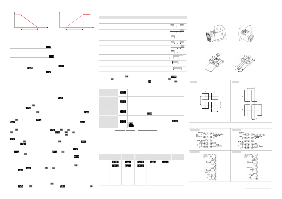
Proportion band (Pb)
(Output percentage)
Heating process
(Temperature)
100%
0%
SV+Pb
SV
Proportion band (Pb)
(Output percentage)
Cooling process
(Temperature)
The bigger the parameter P, the less possible that the heating will exceed the SV and the longer it will take for the
temperature to reach SV. This is suitable for the control system with faster reaction speed. On the contrary, the
smaller the parameter P, the more possible that the heating will exceed the SV and the shorter it will take for the
temperature to reach SV; however, unstable control is more likely to occur. Smaller P is suitable for the control
system with slower reaction speed.
How to set up the parameter of integration time I
: The bigger the value I, the longer the integration time, as
well as the time to reach the SV. Unstable control is also less likely to occur. On the contrary, the smaller the value I,
the shorter the integration time, as well as the time to reach the SV. Unstable control is thus more likely to occur.
How to set up the parameter of differentiation time D
: The bigger the value D, the faster reaction speed and
repression power DTD has for the external interference. However, if D is too big, the repression power that is also
too big will result in out of control of the situation.
Parameters for PID control: The default integration output volume
is to allow the temperature to fast reach
the SV. The parameter
is for compensating the steady error in PD control. The two parameters are the
output percentages when the input reaches the SV. Assume the output percentage is 20% when PV = SV, the best
setting for this parameter is 20.0. The parameter
can be a reference value when being auto-tuned. It can
also be adjusted manually.
h
PID Programmable Control
!
PID programmable control offers 8 steps for you to plan for the temperature control program. You can set up your
own number of steps and times of execution and directly monitor the current executing step, remaining time and the
current SV. There is only 1 group of PID parameter settings and by the first step, you can directly control the
temperature to the SV. You can also set up the control status that after the program ends, DTD will either stop the
output or stay at the last SV.
Setting up the parameters in the program: To set up the parameters in the program, you have to first enter the initial
setting mode and set the control mode as programmable control
to further display the parameters which
you can set up.
In the operation mode, press
and enter the regulation mode. PV will display the parameter of the number of
steps to be executed
. Maximum 8 steps can be planned in this parameter.
After the setup is completed, press
to display the parameters for setting up the execution loops
. The
range of this parameter is 1 ~ 99, e.g. 2 means executing twice.
Press
to setup the parameter
for the action of DTD after the program ends. Set this parameter as
, indicating that the control output will stop after the program ends. Set this parameter as
, indicating
that DTD will stay at the last step before the program ends.
Press
and display the parameter of SV of step 1
. Use
and
to set up the SV. Next, press
to display the parameter of the executing time of step 1
. Use
and
to set up the time (unit:
minute; Max. 9,999 minutes). After the setup of step 1 is completed, press
to set up the parameters (SV and
executing time) of the next step. Please note that the number of steps is decided by the setting of the parameter
. The number of steps that exceeds the setting will not be displayed on the screen of DTD during the
operation. Press
to return to the operation mode and press
to display the parameter
. Set this
parameter as
and execute the control. DTD does not offer pause function; all executions start from step 1.
In the operation mode, on the SV display, you can monitor the present value (default)
, remaining executing
time
, or the executed number of loops and steps
. Use
to switch between different monitoring
modes and press
to display the selected monitoring mode. When the execution of the program ends, the
remaining executing time will be displayed as “0” and the executed loops and steps as
.
h
Setting up Manual Control
Select manual control in the control mode and set up the control cycle first. Next, press
repeatedly in the
operation mode until
is displayed. Use
and
to modify the output percentage. During the
execution
, the output percentage will vary upon different output percentage settings. The output setting will
be saved and the saved setting will be adopted next time when DTD is switched on. The default setting is 0%.
Alarm Settings!
h
Setting up Alarm Mode
!
DTD offers 9 alarm modes and 4 alarm options. Press
for more than 3 seconds and PV will display the
parameter
. Press
for 6 times to display the parameter
for setting up alarm modes. Use
to select a desired alarm mode. Mode 9 is only available in the programmable control mode. See the table below
for the explanation of every alarm mode.
Mode
Alarm Type
Alarm Output Operation
0 No
alarm
Off
1
Deviation upper- and lower-limit:
Alarm will be enabled when the PV exceeds SV + AL-H or falls below SV -
AL-L.
ON
OFF
SV - (AL-L) SV
SV + (AL-H)
2
Deviation upper-limit:
Alarm will be enabled when the PV exceeds SV + AL-H.
ON
OFF
SV
SV + (AL-H)
3
Deviation lower-limit:
Alarm will be enabled when the PV falls below SV - AL-L.
ON
OFF
SV - (AL-L)
SV
4
Absolute value upper- and lower-limit:
Alarm will be enabled when the PV exceeds AL-H or falls below AL-L.
ON
OFF
AL-L
AL-H
0
5
Absolute value upper-limit:
Alarm will be enabled when the PV exceeds AL-H
ON
OFF
AL-H
0
6
Absolute value lower limit:
Alarm will be enabled when the PV falls below AL-L.
ON
OFF
AL-L
0
7
Hysteresis upper-limit:
Alarm will be enabled when the PV exceeds SV+AL-H and disabled when the PV
falls below SV+AL-L.
SV + (AL-H)
ON
OFF
SV SV + (AL - L)
8
Hysteresis lower-limit:
Alarm will be enabled when the PV falls below SV - AL-H and disabled when the
PV exceeds SV - AL-L.
SV - (AL-H)
ON
OFF
SV
SV - (AL - L)
9
Alarm will be enabled only during the execution of the program.
ON
OFF
Prog. Start
Prog. End
h
Setting up Alarm Option
!
To set up the alarm function, press
after you have set up the alarm mode and the parameter
will be
displayed. Use
to set up the desired option and the parameter to be set will flash. Press
again to
change the setting. When the parameter is flashing, you can press
to move to other digits. Press
to
complete and save the setting. The initial setting of the alarm option is 0000, i.e. all alarm options are not enabled. If
you need to enable all the alarm options, set the parameter to 1111.
Standby alarm output
Set the first digit in right hand side as 1 to enable the standby mode. The
alarm output will be enabled when the PV is SV± 2 and the system is in
execution.
Alarm output inversion
Set the second digit in right hand side as 1, when the alarm output is
enabled, the alarm output contacts will be normally open. When there is no
alarm output, the relay terminals will be short-circuit. Please be noted that
the alarm indicator only relates to whether the control criteria are true and
has nothing to do with the alarm output contact.
Holding alarm output
Set the second digit in left hand side as 1 to hold the alarm output. In this
function, after the alarm output is enabled, the alarm will keep being
enabled unless you stop
the operation of DTD.
Displaying alarm peak
value
Set the first digit in left hand side as 1 to display the peak value. When the
alarm output is enabled, DTD will be able to record the highest and lowest
alarm temperature and display the two values in parameter
and
. Before the alarm is enabled, the parameter will be displayed as
. The values will not be kept after the power of DTD is switched off.
Note: DO NOT use standby alarm, holding alarm and displaying alarm peak values in alarm mode 7, 8 and 9.
h
Exceptions in Alarm Functions
1. When DTD is switched on, in STOP state or alarm mode 0, the alarm will not be enabled and the standby
status will be cleared.
2. Where there is no input sensor connected to DTD or input error, the status of the alarm output will remain.
3. Modifying alarm mode will not clear the standby status. The standby alarm will only be cleared when you STOP
the operation of DTD and re-RUN it again.
Error Display!
Error
Status
Initializing
No Input
Sensor
Connected
Input Signal
Error
Exceeding
Upper Limit
Exceeding
Lower Limit
Exceeding
Setup Range
PV
Flashing
SV
N/A N/A N/A
Note
Initializing.
Displaying
software
version and
the type of
input sensor.
The input
voltage is too
big,
connecting to
empty
terminal, or
incorrect
sensor.
Cannot get
temperature
value, ADC
input error.
The
displayed
value
exceeds
10,999.
The
displayed
value is
smaller than
-1,999.
The input
exceeds
TP-H (Max.
temp), TP-L
(Min. temp),
or the range
of the input
sensor
selected.
How to Mount
!
1. Insert DTD into the panel cutout.
2. Insert the mounting bracket into the mounting groove at the top and bottom of DTD.
3. Push the mounting bracket forward until the bracket stops at the panel wall.
4. Tighten the screw.
How to Install Mounting Bracket
!
Panel Cutout
!
DTD4848
65.0 min.
6
0
.0
m
in
.
45
+0.6
0
4
5
+
0
.6
0
DTD4896
60.0 min.
1
2
0
.0
m
in
.
+0.6
-0
9
1
.5
+
0
.6
-
0
Terminals
!
DTD4848R0
DTD4848V0
DTD4896R0
DTD4896V0
The content of this instruction sheet may be revised without prior notice. Please consult our distributors or
download the most updated version at http://www.delta.com.tw/industrialautomation