Figure 54 – Hypertherm Powermax30 XP Service Manual User Manual
Page 117
Powermax30 XP Service Manual 808150 Revision 1
117
6 – Power Supply Component Replacement
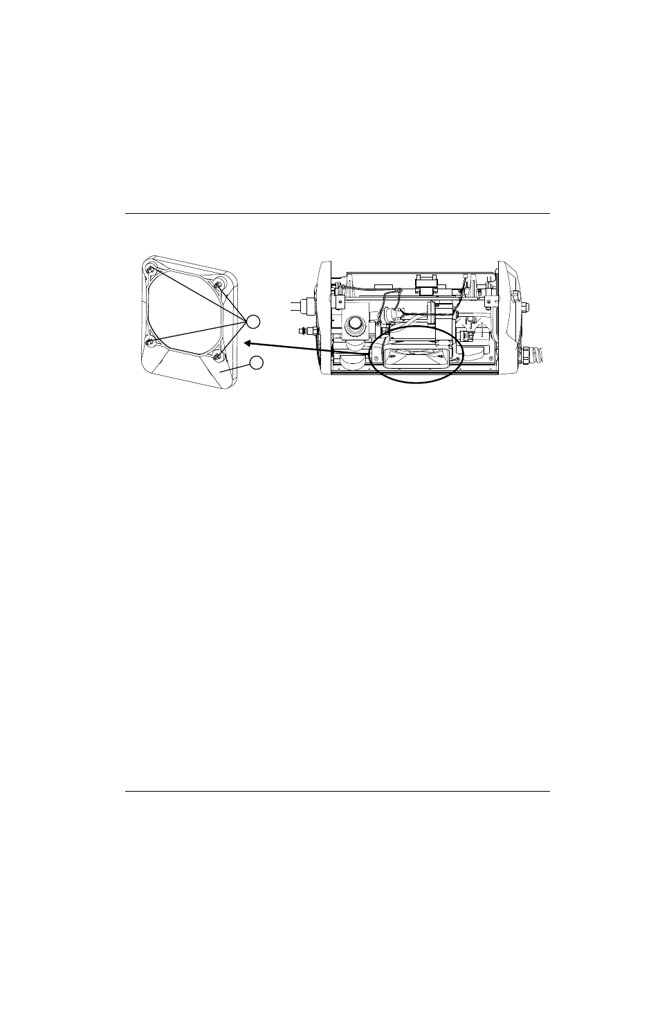
Figure 54
4. Remove the retaining screw from each corner of the fan.
5. Slide the old fan out of the power supply and set it aside.
6. Slide the new fan into place. Orient the fan so that the red-and-black wires are at the upper left corner of the fan (the
side closest to the rear panel).
7. Reinstall the four retaining screws and tighten them to 11.5 kg-cm (10 inch-pounds). Use the new screws included
in the kit if needed (075711).
8. Orient the new fan plenum so that the wider end is at the bottom, and snap it into place. (See Figure 55.)
9. Route the fan’s red-and-black wires through the notch in the top of the center panel that is nearest the solenoid valve.
(See
Figure 55.)
10. Attach the connector for the red-and-black wires to J5 on the power board. (See Figure 53 on page 116.)
2
1