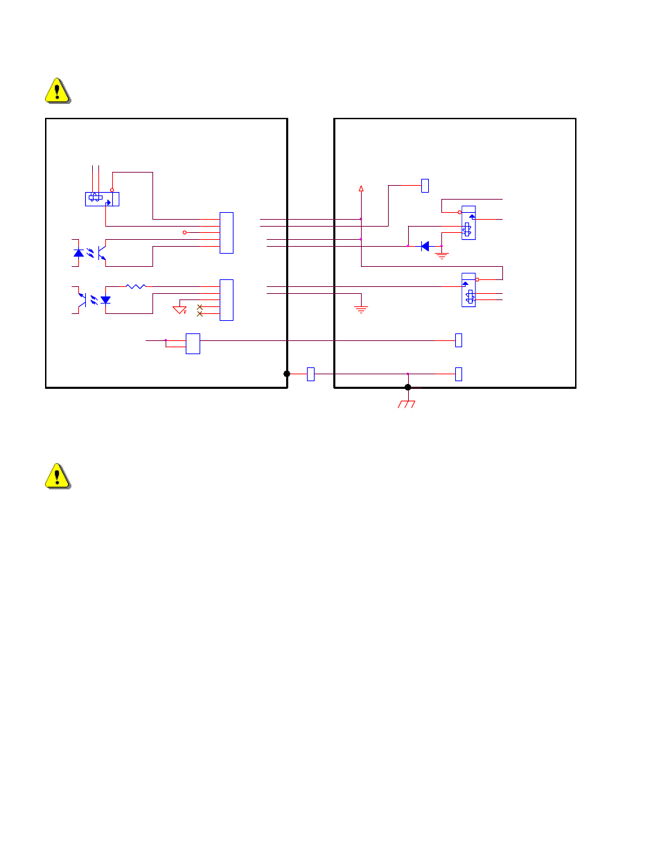
External plasma supply (using external +24v), Sensor phc plasma interface i/o, Figure 18: plasma interface connections – Hypertherm PHC Sensor User Manual
Page 36
36
Sensor™ PHC Operation and Setup Guide
WARNING! For safety and proper operation this unit must be connected to positive ground.
Work
Positive Ground
Electrode (Neg)
GND_External
+12V Field
PLASMA START (+24V)
HOLD
IGNITION
TRANSFER
J1
1
2
3
4
5
HLD-
J3
1
2
3
4
5
HLD+
XFR-
RELAY
OPTO
OPTO
3300
External Plasma Supply
(using External +24V)
STR
STR
XFR+
+24V External
GND_External
RELAY 24V coil
RELAY
DIODE
1
2
Electrode (Neg)
Sensor PHC Plasma
Interface I/O
Figure 18: Plasma Interface Connections
WARNING:
Observe signal polarities when connecting to optocouplers. Do not exceed 24Vdc on any signal lines. Do not
exceed 30mA current from any input or output. Do not exceed 50mA total current drawn from Sensor™
internal +12V field supply. Failure to observe these warnings could damage the unit.
- EDGE Pro Ti Shape Cutting Control Rev.2 (288 pages)
- 80669J Rev.3 (304 pages)
- HD3070 Plasma Arc Cutting System w/ Manual Gas Console (281 pages)
- MAXPRO200 Rev.2 (294 pages)
- MicroEDGE Pro Shape Cutting Control Rev.2 (182 pages)
- Powermax1650 (317 pages)
- HPR260 Auto Gas Preventive Maintenance Program Rev.4 (288 pages)
- Shape Cutting Control (66 pages)
- HTA Rev 6.00 Operators Manual (212 pages)
- HTA Rev 7.00 Install Guide (242 pages)
- THC Control Board Replacement (13 pages)
- THC Plasma Interfacer Upgrade (9 pages)
- THC X-Y Table Product Configuration (20 pages)
- D845GERG2 (128 pages)
- MRT2 (64 pages)
- MRT (98 pages)
- Duramax Hyamp Long Handheld Torches (92 pages)
- Duramax Hyamp Robotic Torch (74 pages)
- HyIntensity Fiber Laser Rev.3 (240 pages)
- PCBS-0124 (70 pages)
- SuperMicro 370SBA 533Mhz (90 pages)
- LR2075 (56 pages)
- Phoenix 8.0 (585 pages)
- LH2125 (60 pages)
- HD3070 w/ Automatic Gas (35 pages)
- HD3070 w/Manual Gas (43 pages)
- HD4070 Rev.8 (278 pages)
- HD4070 Product Configuration (88 pages)
- HPR800XD Manual Gas Preventive Maintenance Program Rev.1 (32 pages)
- HPR800XD Manual Gas Preventive Maintenance Program Rev.1 (33 pages)
- HPR800XD Manual Gas Rev.2 (368 pages)
- HPRXD Short Torch with Integrated Lead Rev.1 (30 pages)
- HT4001 (59 pages)
- DuraChill 5 HP Air-Cooled Chiller For Hypertherm (29 pages)
- HT4001 Air Injected Water Muffler System (40 pages)
- H601 Power Supplies (62 pages)
- MAX200 Remote Switch (9 pages)
- HT4100 Plasma Arc Cutting System Operating (50 pages)
- HT4001 Plasma Arc Cutting System (259 pages)
- HSD130 HySpeed Plasma (233 pages)
- HySpeed HT2000 Plasma Arc Cutting System Rev.7 (53 pages)
- HySpeed HT2000 Plasma Arc Cutting System Rev.27 (289 pages)
- MAX200 Water Muffler (39 pages)
- HT2000LHF Product Configuration (23 pages)