Phc interface signals, Example inputs, Example outputs – Hypertherm PHC Sensor User Manual
Page 29: Sensor phc internal circuitry, Figure 14: general interfacing examples, External circuitry, Outputs external circuitry, Inputs
Section 2: Installation and Setup
29
PHC Interface Signals
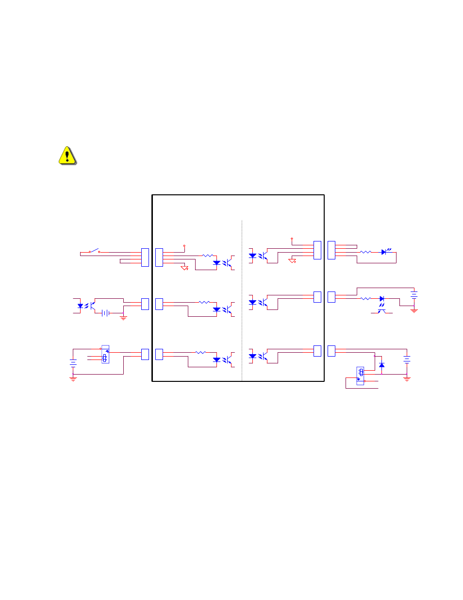
Most of the PHC interface signals are through optoisolators. Figure 14 shows the details of connecting the IO
to external switches, relays, transistors, and other circuitry. The figure shows examples using both the
internally available isolated +12V source and using an external voltage source. Do not use an external voltage
higher than +24V with inputs without adding some additional series resistance.
Note: The “Plasma Start” output to the plasma power supply is a relay dry contact closure.
WARNING!
Do not exceed 24V or 30mA in or out of any optoisolator. Observe correct signal polarity to prevent damage.
+OUT
DIODE
SWITCH
RESISTOR
LED
-OUT
24V
24V
+
GND_External
GND_External
+
RESISTOR
+12V Field
+IN
24V
-IN
+
RELAY
External Circuitry
OPTO ISOLATOR
-IN
Use Internal PHC +12V Supply
Use External +24V Supply
+OUT
-OUT
+OUT
-OUT
Use Internal PHC +12V Supply
+IN
Use External +24V Supply
Sensor PHC Internal Circuitry
24V
-IN
Outputs
External Circuitry
OPTO ISOLATOR
Inputs
Example Inputs
3300
+IN
3300
+
Use External +24V Supply
+12V Field
3300
RELAY
GND_External
Use External +24V Supply
GND_External
Example Outputs
Figure 14: General Interfacing Examples