2 setting up – Guralp Systems CMG-EDU User Manual
Page 9
Operator's guide
2.2
Setting up
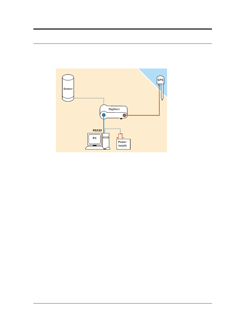
Once you have chosen suitable locations for the sensor, digitizer and
GPS, you need only connect the various components and supply them
with power. The digitizer and sensor will begin working immediately.
•
Connect the grey cable attached to the sensor to the SENSOR
socket on the digitizer.
•
Connect the brown cable attached to the GPS unit to the GPS
socket on the digitizer.
•
The remaining blue and grey cables are joined together at a 9-
pin RS232 socket. Connect this socket to your PC’s serial
connector.
•
The grey cable from the RS232 connector ends in red and black
wires. Connect the black wire to the negative (–) terminal of the
power supply, and the red wire to the positive (+) terminal.
•
The blue cable from the RS232 connector ends at a blue socket.
Connect this to the DATA plug on the digitizer. Do this step last
– an intermittent power supply can damage the digitizer, so it is
best to make sure the wires to the power supply terminals are
securely connected before you connect the digitizer.
•
When everything is connected, the digitizer should be drawing
around 50 mA from the power supply. You can measure this
either directly from the power supply unit (if it has the facility)
or by connecting a 5 W-rated, 1 Ω resistor in series with the
positive terminal and measuring the voltage drop across it: 50
October 2005
9