Gullco GK-200-RLx-L User Manual
Page 11
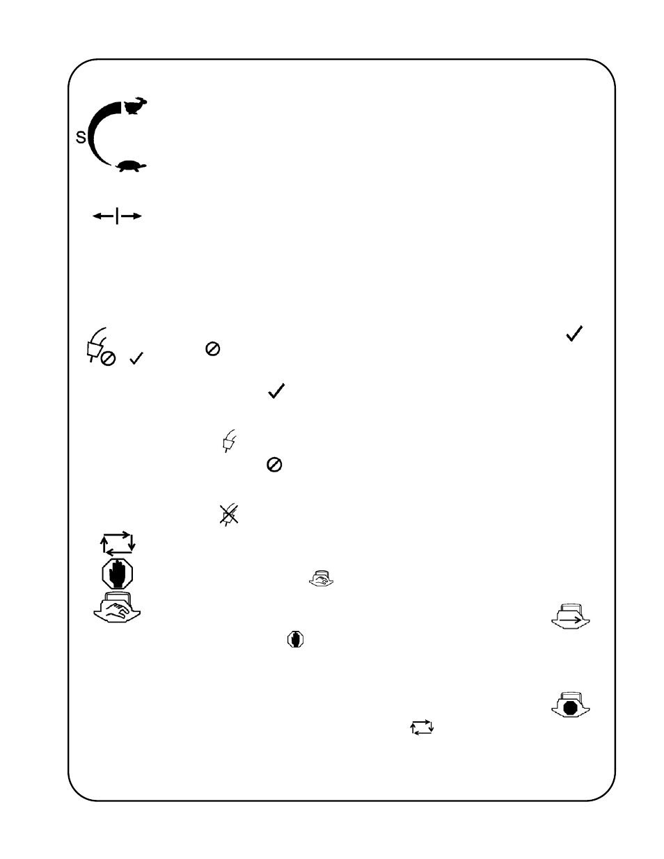
9
The S rotary switch increases (clockwise adjustment) or decreases (counter-
clockwise adjustment) the oscillation stroke speed. The increments of adjustment
and the minimum and maximum allowable stroke speeds are dependent on the type
of Oscillator Head used and the preferred units of measurement (see the Technical
Manual, GD-057-T for details). The current value is displayed on the LCD screen.
Speed adjustments can be changed at any time before or during operation and will
take effect immediately.
The Center Position Adjustment rotary switch will allow the operator to jog the center
position (B location) either to the left or to the right. This rotary switch can be used to
position the welding gun prior to oscillation when the Manual/Hold/Auto switch is in
the Manual position. To make adjustments (steering) while welding, rotate the
Center Position Adjustment rotary switch in the appropriate direction until the centre
of the oscillation has moved to the desired location. The size of these centre
adjustment (steering) increments can be programmed to be as large or small as
preferred (see the Technical Manual, GD-057-T for details).
The Arc Enable/Disable switch will allow the operator to either Enable (
) or
Disable (
) the arc activation signal to the welding equipment. This Enable/Disable
selection can be made at any time and will take effect immediately.
When Enabled (
), the arc activation signal will be energized while-ever the
oscillator is running. When the arc activation signal is energized, the arc
activation signal icon in the lower left corner of the LCD screen will appear as
follows:
When Disabled (
), the arc activation signal will de-energize (if applicable) and
remain de-energized. While ever the arc activation signal is de-energized, the
arc activation signal icon in the lower left corner of the LCD screen will appear as
follows:
The Manual/Hold/Auto switch is used to start and stop the oscillator equipment as
well as interfacing with the “KAT”
®
travel carriage.
In the Manual position (
), the arc activation signal and the oscillator head
are inactive, and the “KAT”
®
carriage will operate manually. The carriage release
icon on the lower right corner of the LCD screen will appear as follows:
The Hold position (
), over-rides all other controls and when activated will
apply the Hold (stop) signal to the “KAT”
®
carriage control, and will disallow any
further operation of the “KAT”
®
while ever it is in this state. The arc activation
signal and the Oscillator Head remain inactive in this mode. The carriage hold
icon on the lower right corner of the LCD screen will appear as follows:
When placed in the Auto cycle position (
), the arc activation signal will
energize (only if the Arc Enable/Disable switch is in the Enable state) and the
Oscillator Head will start its oscillation motion. After the programmable Travel
Start time delay the oscillator control will deactivate its Hold (stop) command to
the “KAT”
®
carriage control, thus allowing it to travel. While ever the Hold (stop)