Gullco GK-200-RLx-L User Manual
Page 10
8
0.0
B
4
0.0
1.06
A
0.0
72
C
CM
W
S
CM/MIN
OSCILLATOR CONTROL
A highly sophisticated, yet easy to use, multi-processor based
control drives a high torque, high resolution, low vibration
stepper motor located in the Oscillator Head, allowing the
welding gun to be moved in a precise reciprocative manner.
The control interfaces with the “KAT”
®
carriage travel and the
trigger signal of the welding equipment. By controlling the
oscillation width, speed, positioning and dwell patterns as well
as the timed activation/deactivation of the “KAT”
®
carriage
travel and the welding process, the quality and appearance of
the weld can be tuned to perfection.
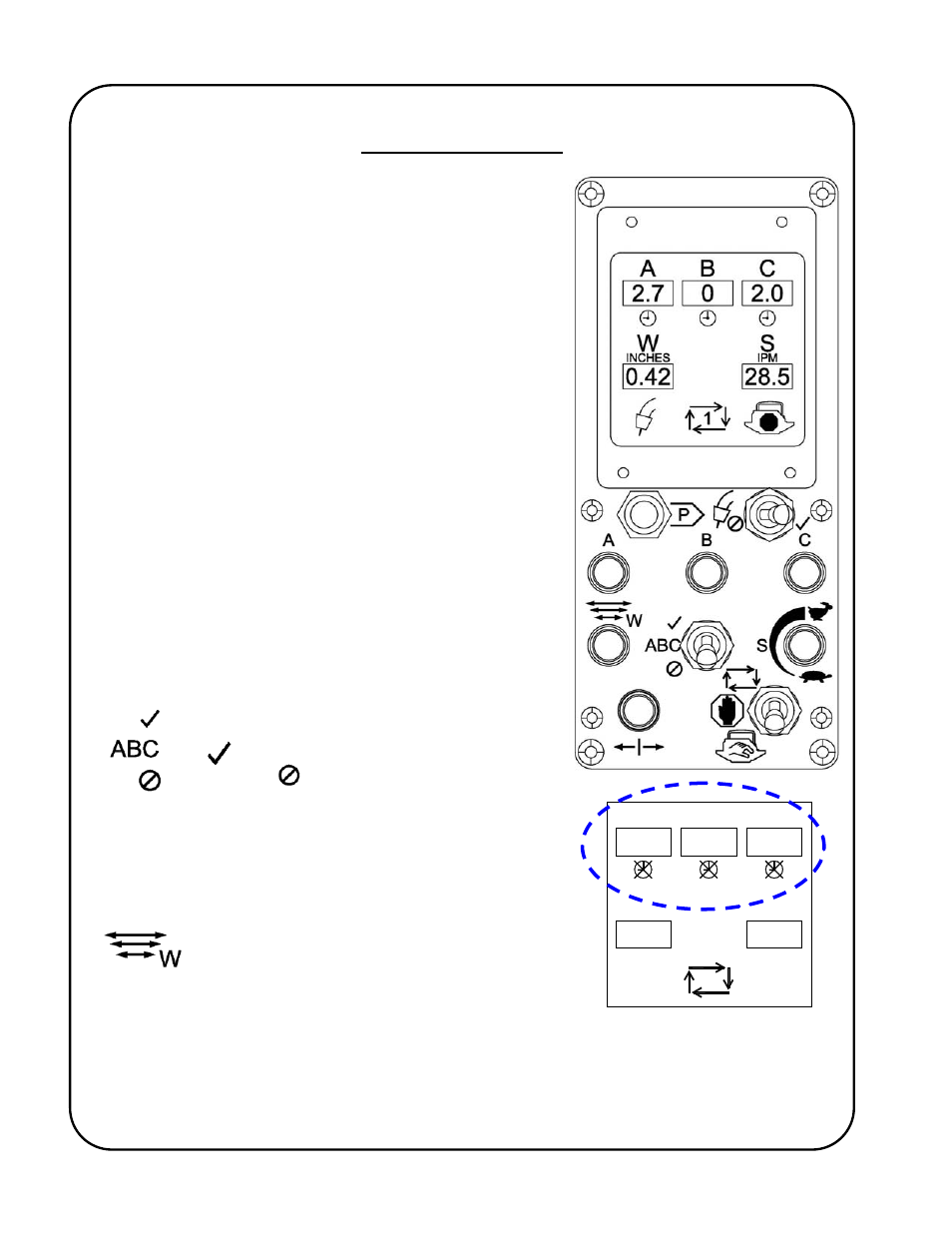
The A, B & C rotary switches will increase
(clockwise adjustment) or decrease (counter-
clockwise adjustment) the A, B & C location
dwells respectively by 0.1 second increments,
from a minimum of zero up to a maximum of
9.9 seconds. The current values are displayed
on the LCD screen. These adjustments can be
changed at any time before, or during,
operation and will take effect on the next
relevant dwell location. The orientation of the
ABC locations of the Oscillator Head can be
altered (programmed) to match the orientation
of the control (see the Technical Manual, GD-
057-T for details).
The Dwell Enable/Disable switch will allow the
oscillator to perform the A, B & C location dwell
timing cycles while running when Enabled
(
) or will not perform the dwells when
Disabled (
). This Enable/Disable selection
can be made at any time and will take effect
immediately. When disabled the LCD screen
will show all dwell times as zero and the dwell
disabled icons crossed-out, as shown
adjacent:
The W rotary switch increases (clockwise
adjustment) or decreases (counter-clockwise
adjustment) the total width of the oscillation
stroke (A to C). The increments of adjustment
and the minimum and maximum allowable stroke
widths are dependent on the type of Oscillator
Head used and the preferred units of measurement (see the Technical Manual, GD-
057-T for details). The current value is displayed on the LCD screen. Width
adjustments can be changed at any time before or during operation and will take
effect on the next travel past the B location. Note:- there is a width range where the
oscillation stroke is too small to permit A, B & C dwells to work.
A
B
C