Gullco GM-03-300 User Manual
Page 12
10
Programming The Automatic Cycle Parameters/Variables
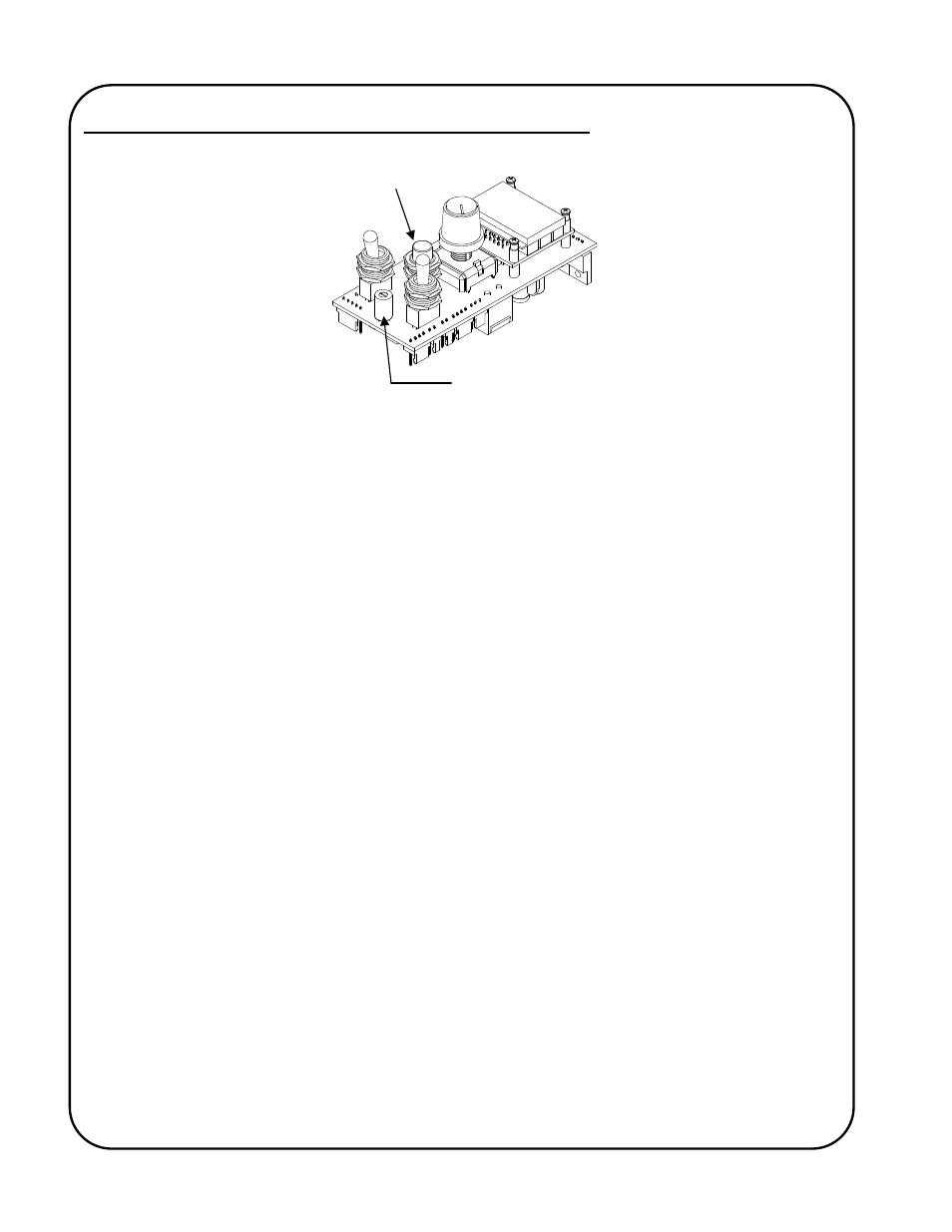
The Program Variable Selector Switch is used to select the different programmable parameters that
allow the operator to change their values and settings and so define how the automatic cycle will
function. The Program Variable Selector Switch is located between and below the Run/Stop switch
and the Forward/Neutral/Reverse switch of the GSP control. The Program Variable Selector Switch
on the GM-03-300 model is extended through the faceplate for easy access. The recessed selector
switch on the GM-03-350 model requires the removal of a hole plug in the faceplate for access and
a small flat-bladed screwdriver for adjustment.
Zero (0) (top dead centre) is the normal operating location for the switch. When in any position
other than zero (0) the control is in programming mode, the round, Auto Cycle Mode L.E.D. in the
bottom right hand corner of the display will flash and the motor control will not allow normal
operation.
To make changes to the program variables, remove the hole plug on the front face which covers the
recessed Program Variable Selector switch (where applicable). With the power turned on and the
Run/Stop switch in the Stop position, rotate the Program Variable Selector switch to the variable
(parameter) to be altered (the Auto Cycle Mode L.E.D. will flash on and off). The number of the
variable parameter will be displayed when the Forward/Neutral/Reverse switch is in the Neutral
position. I.e. “P. 1”, “P. 2”, “P. 3”, etc. To see the current value/setting of the variable, place the
Forward/Neutral/Reverse switch in either the Forward or Reverse position. To increment (increase)
the value/setting, place the Forward/Neutral/Reverse switch in the Forward position and press the
Cycle Push Button. To decrement (reduce) the value/setting, place the Forward/Neutral/Reverse
switch in the Reverse position and press the Cycle Push Button. Pressing the Cycle Push Button
briefly will increment/decrement the value/setting by one, whereas keeping the Cycle Push Button
depressed will scroll through the values/settings until released. The speed display and or the
individual L.E.D.’s will indicate the chosen value/setting. When all of the program variables are set,
place the Program Variable Selector switch back to the zero position (the Auto Cycle Mode L.E.D.
will stop flashing) and re-insert the hole-plug (where applicable).
The values/settings of the variables are stored on the product/application specific micro-processor
chip. If the chip is replaced, the values/settings of the variables will need to be re-entered.
Cycle Push Button
Program Variable
Selector Switch