Multiple actuator (parallel) wiring – Greenheck S73 Series User Manual
Page 8
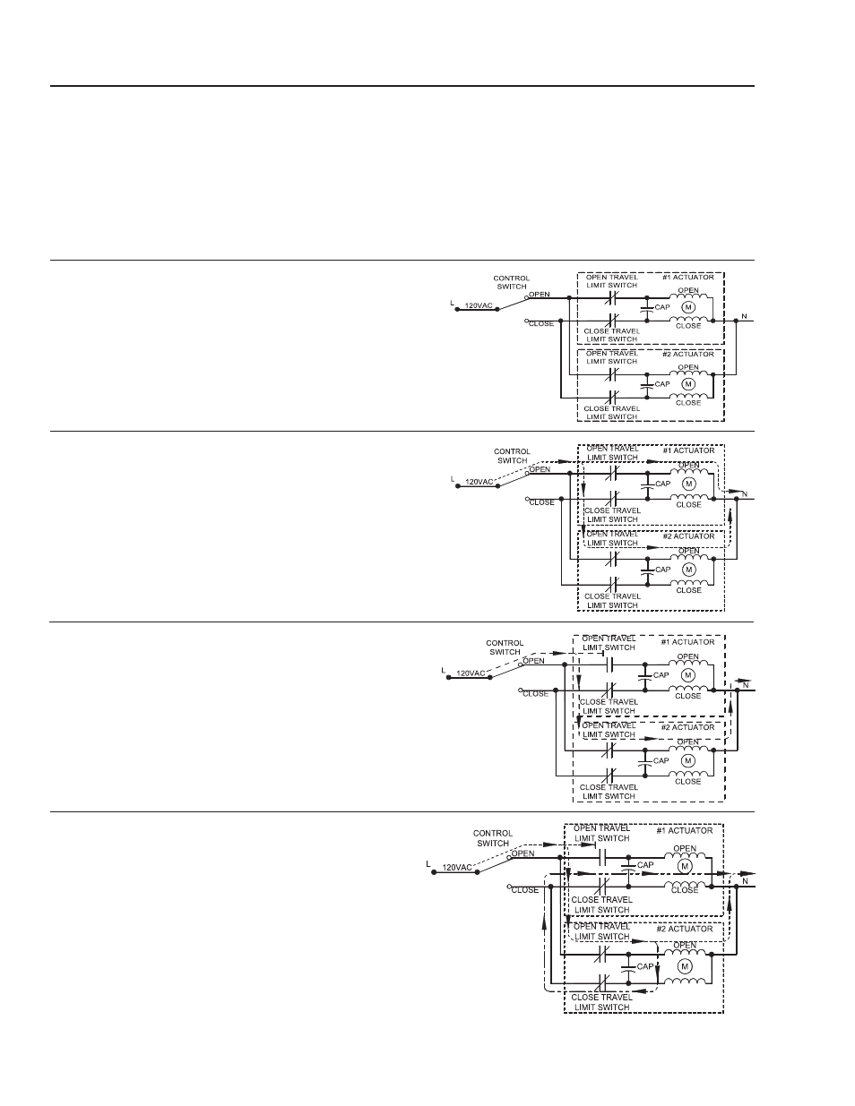
Multiple Actuator (Parallel) Wiring
A voltage is present on both motor windings, these voltages
are out of phase and different in magnitude. If these windings
are connected to one another as shown in the INCORRECT
diagrams, this will interfere with the motor performance. Use
a multiple pole switch as shown in the CORRECT diagram.
incOrrect cOnnectiOns
A. No supply on terminal L.
B. Control switch in “Open Run Position”
C. Both actuators in a mid-travel position. i.e. Their open
& close travel switches are closed, allowing them to
operate in an open or close travel direction.
*The following three diagrams show progressive
result of parallel wiring.
D. 120VAC source applied, both motors start to run “open”.
(Shows current flow)
E. #1 actuator runs fully open and its travel limit switch
opens circuit. This actuator stops (perhaps only for a
short time!). #2 actuator continues to run open.
(Shows current flow)
F. The other “Back Feeding” current path existing between
the actuators is shown.
G. Though actuator #1 had come to rest (full open), it can
and does get current flowing through its close travel leg
via this “Back Feeding” current from #2 actuator.
This causes actuator #1 to run a couple of degrees in the
closed direction, #2 actuator will then reach its fully open
position. If left running for a “good” period, both actuators end
up driving each other OPEN-CLOSED at strange positions.
(Shows current flow)
(Shows other “Back Feeding” current flow)
BRAY Series 73 Electric Actuator
Operation and Maintenance Manual
6