Switch – Greenheck S73 Series User Manual
Page 11
f
ield
install
.
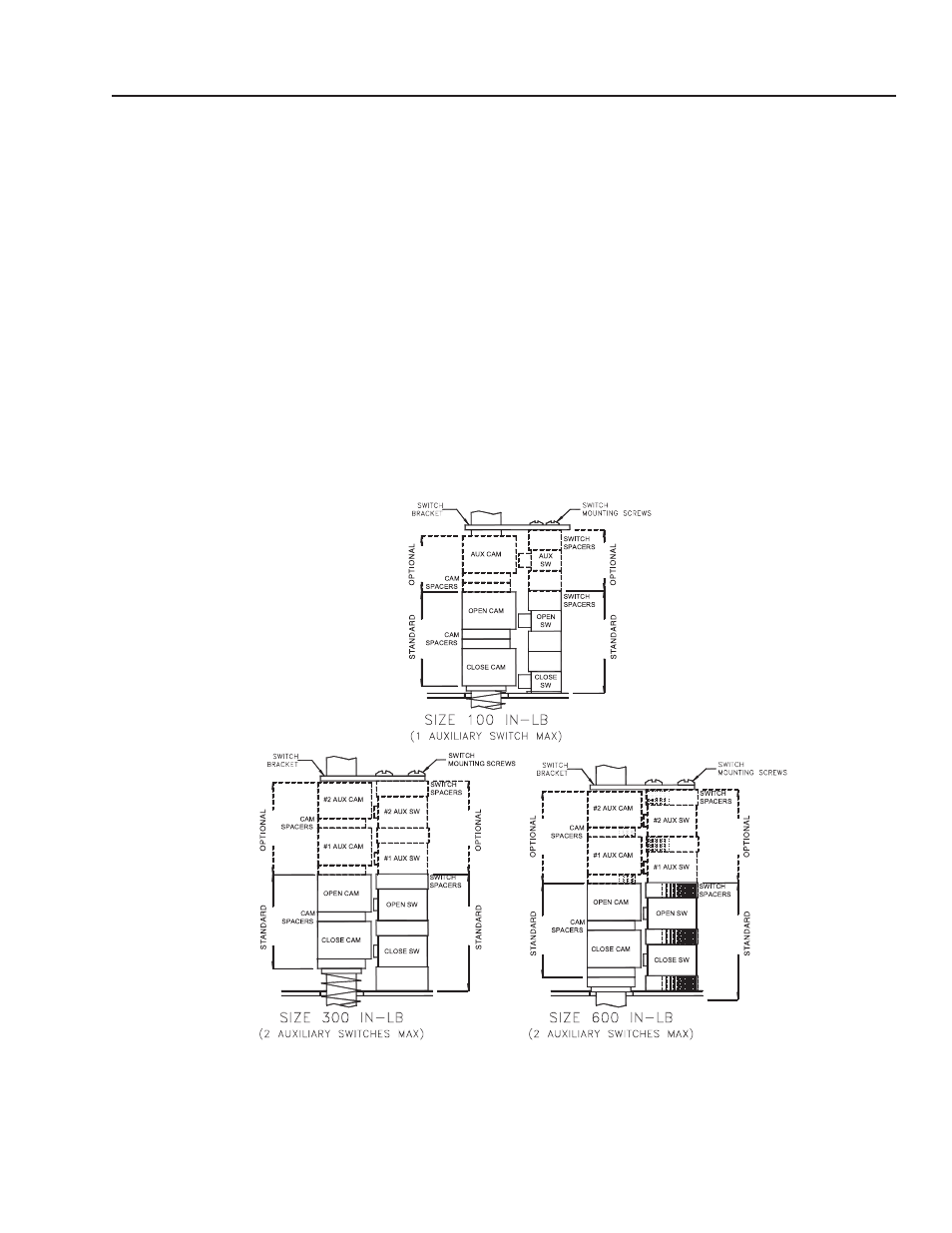
Of
auxiliary
switch (
es
)
The maximum allowable auxiliary switch configuration is
shown in the illustrations below for each size of actuator.
a
uxiliary
s
witch
K
it
c
Onsists
O
f
:
1. Switch with flying leads
2. Switch spacers
3. Cam with set screw
4. Cam spacers
5. Pan head screw, phillips drive
t
OOls
r
equired
For terminal wiring Screwdriver, 3/16” flat tip blade
i
nstallatiOn
P
rOcedure
:
For switch mounting Screwdriver, No. 1 phillips
1. Remove switch mounting screws & discard
2. Remove switch bracket & retain for use later
3. Install auxiliary cam(s) and spacers as shown
4. Install auxiliary switch(es) and spacers as shown
5. Reinstall switch bracket
6. Install longer switch mounting screws from kit
7. Connect switch wiring to terminal strip per wiring
diagram
8. Adjust cams as required
BRAY Series 73 Electric Actuator
Operation and Maintenance Manual
9
- VCD-40 Extension Pin Kit 316SS (475290) (2 pages)
- 331-2856, 332-2856 - Siemens 6 Actuator (454206) (2 pages)
- 331-2976, 332-2976 - Siemens 4 Actuator (454202) (2 pages)
- 331-4551, 332-4551 - Siemens 3 Actuator (454201) (2 pages)
- Adjustable Pressure Controller (468292) (3 pages)
- 7800 Series Relay Modules (12 pages)
- Standard Control - MSSC (476372) (4 pages)
- NFB Series Actuators External Mount (464236 IOM) (2 pages)
- GND Series External Mount (473723) (4 pages)
- Amplifier for 7800 Series Relay Module (8 pages)
- APEX Curbs (462831) (4 pages)
- AMD-xx-TD Transmitter (35 pages)
- Blade Seal Repalcement (HCDR Series) (1 page)
- VCD (463384) (12 pages)
- BAPI Zone Pressure Touch (ZPT) Sensor (6 pages)
- VCD (463384) (10 pages)
- Blade Seal Replacement (HCD Series) (2 pages)
- BR Series - Counterweight Adjustment (469420) (4 pages)
- Leakage Rated Ceiling Radiation Dampers (475063 IOM). (32 pages)
- Canopy Hoods (452413 IOM) (36 pages)
- Clean-Out Port Kit (472428) (1 page)
- Centrifugal (CSW, BIDW, AFDW), Industrial (IPA, IPO, IPW) and Filtered Supply (LSF) (463687) (12 pages)
- Close Indicator Switch for Fire Dampers (474050) (1 page)
- Concrete Floor with Steel Deck Supplement (463562) (1 page)
- CRD-3XX and CRD-7XX Series for SP fans (452832) (2 pages)
- VCD (463384) (8 pages)
- VCD (463384) (4 pages)
- Single Side Retaining Angle (52 pages)
- DG / DGX with Pilot Ignition (463555 IOM) (Pre-2008) (48 pages)
- DG / DGX with Direct Spark (470652) (40 pages)
- Digital Temperature Interlock (474750 IOM) (Pre November 2012) (8 pages)
- DGK (468695) (20 pages)
- DG / DGX with Pilot Ignition (463555 IOM) (Pre-2008) (52 pages)
- Double Gland Axle Seal Replacement (1 page)
- Dock Arm Kit (475367) (4 pages)
- Duct Heaters Series IDHB and IDHC (478052) (8 pages)
- EHH-601D, Channel Installation (474643) (10 pages)
- EHH-601D, Channel Installation with VCD-40 Damper (474644) (8 pages)
- EHH-601D, Flange/Sleeve Installation (474641) (8 pages)
- GM Series (468391) (4 pages)
- EHH-601D, Flange/Sleeve Installation with VCD-40 Damper (474642) (8 pages)
- El-O-Matic E and P Series (12 pages)
- Energy Recovery Filter Hood System (8 pages)
- ERV-582/120 Curbs (460988) (4 pages)
- ESD-635D, Chanel Installation (474639) (10 pages)