Warning – Greenheck S73 Series User Manual
Page 6
I
nsTallaTIOn
M
Ounting
tO
a
V
alVe
All Bray Series 73 electric actuators mount directly to Bray
butterfly valves. With proper mounting hardware, the S73
actuator can be installed onto other quarter-turn valves or
devices. For horizontal installation, the standard mount-
ing position aligns the actuator parallel and upright to the
pipeline. If the actuator is to be mounted on a vertical
pipe, it is recommended that the unit be positioned with
the conduit entries on the bottom to prevent condensa-
tion from entering the actuator through the conduit. In
all cases, the conduit should be positioned to prevent
drainage into the actuator.
The actuator should be mounted to the valve as follows:
1. Manually operate the actuator until the output shaft of
the actuator is in line with the valve stem. If possible,
use an intermediate position (i.e. valve disc/stem and
actuator half open).
2. Place the proper adapter, if required, onto the valve
stem. It is recommended that a small amount of grease
be applied to the adapter to ease assembly.
3. Mount the actuator onto the valve stem. It may be
necessary to manually override the actuator to align
the bolt patterns.
4. Install the furnished mounting studs by threading
them all the way into the actuator base.
5. Fasten in place with the furnished hex nuts and lock
washers.
m
anual
OverrIDe
OPeraTIOn
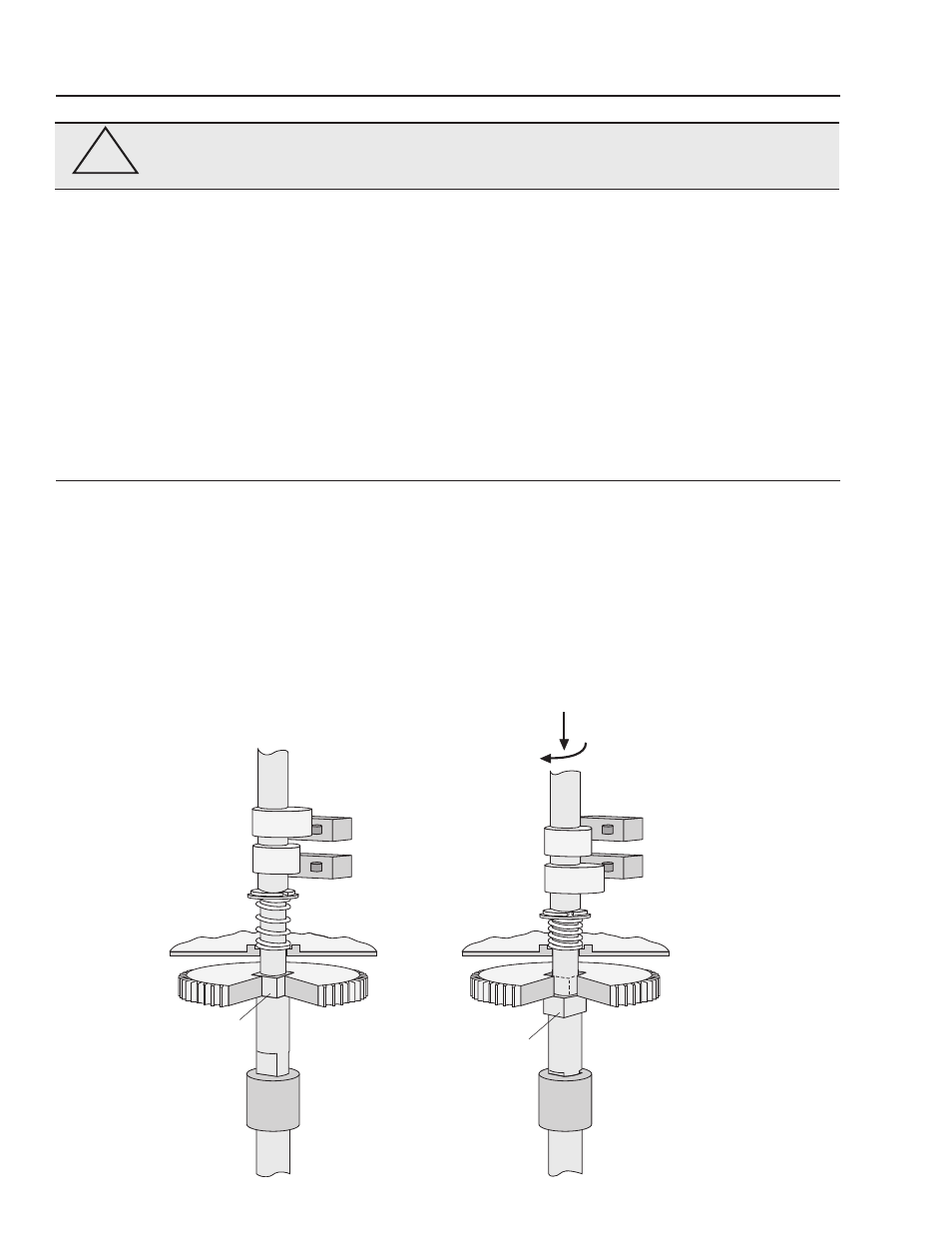
1. Ensure that electrical power to the unit is off.
2. Press valve position indicator down, then release a
few times to ensure ease of movement.
3. Remove the valve position indicator pointer.
4. Using an adjustable wrench, 6” or 12” depending
on actuator size, push down on indicator shaft to
disengage it from output gear, then turn shaft to
required position. Open and Close lettering and a
direction of travel arrow are molded into the hous-
ing for easy reference and permanent position
indication. The double D flats on the indicator shaft
are in alignment with the valve disc position.
5. Return to electrical operation by turning power
on to the unit. The shaft will re-engage the
output gear when electrical power is applied to
the actuator.
6. Replace the valve position indicator pointer.
Open Travel
Switch
Close Travel
Switch
Gear With
Square
Drive Hole
(Cutaway)
Switch Plate
(Cutaway)
Spring
Valve Stem
Gear With
Square
Drive Hole
(Cutaway)
Switch Plate
(Cutaway)
Double D Drive End
of Indicator Shaft
Actuator Drive
Coupling
Valve Stem
Double D Drive End
of Indicator Shaft
Actuator Drive
Coupling
Indicator Shaft
Spring
Snap Ring
Open Travel
Switch
Close Travel
Switch
Open Cam
Close Cam
Square Drive
of Indicator
Shaft
Square Drive
of Indicator
Shaft
Snap Ring
Indicator Shaft
Using an Adjustable
Wrench, Push Down
and Rotate the Indicator
Shaft to Manually Drive
the Actuator & Valve
Series 73 Under Normal
Electrical Operating
Conditions
Open Cam
Close Cam
BRAY Series 73 Electric Actuator
Operation and Maintenance Manual
4
!
WARNING
Turn off all power and lock out service panel before installing or modifying any
electrical wiring.