Notice – Greenheck S73 Series User Manual
Page 5
I
nTrODuCTIOn
The Bray Series 73 is a quarter turn electric actuator with
manual override for use on any quarter turn valve requiring
up to 600 Lb-In of torque. Operating speeds vary between
2 to 60 seconds. Adjusting two cams sets the open and
close travel limit switches. These cams can be adjusted to
allow rotational travel anywhere from 45° to 300°. Standard
Factory setting allows for 90° reversible rotation.
P
rinciPle
O
f
O
PeratiOn
The Series 73 actuator is basically divided into two internal
sections; the power center below the switchplate, and the
control center above the switchplate. Below the switch-
plate the spur geartrain drives an output coupling. The
override mechanism for manual operation is also located
here. Above the switchplate are components requiring
customer adjustment. The indicator shaft assembly, limit
switches, terminal strips, heater, capacitor and motor are
all placed here for easy access. External to the unit are a
highly visible valve position indicator, the unique manual
override shaft and two 1/2” NPT conduit entry ports. The
external finish is a high quality polyester powder coating,
which has exceptional UV as well as chemical resistance.
e
lectrical
O
PeratiOn
The motor used in the Bray Series 73 is a permanent
induction split capacitor design (single phase AC power).
Travel limit switches are mechanical form C (SPDT) are
rated at 10 amp (0.8 PF), 1/2 HP 125 VAC and 3/4 HP
250 VAC. In situations where the torque capacity of the
unit is exceeded to the point where the motor stalls and
overheats, a thermal protector switch built into the motor
windings will automatically disconnect the motor power.
Once the motor cools sufficiently the thermal switch will
reset. The motor has a spring loaded brake that activates
when power is removed from the unit. The brake prevents
the spur gears from being back driven.
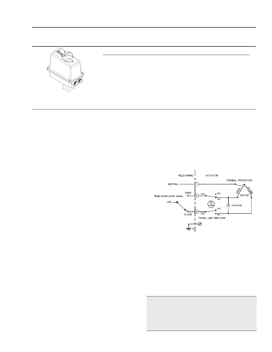
General Electrical Schematic
(Note: the schematic below is for reference only. The actual wiring
diagram for each specific unit is placed inside the actuator cover).
M
echanical
O
PeratiOn
Mechanically, the ratio of the gearmotor determines the
speed of the unit. The gearmotor utilizes high efficiency
spur gears with various ratios for the actuation speeds.
Positioning is determined by an indicator-camshaft linked
to the output coupling.
P
re
-i
nstallatiOn
s
tOrage
Units are shipped with two metal conduit entry plugs to
prevent foreign matter from entering the unit.
nOTICe
To prevent condensation from forming inside these units,
maintain a near constant external temperature and sup-
ply power to the optional heater internal to the unit.
Use this chart as a guide to interpret the S73 electric actuator part number.
P
art
n
uMbering
s
ysteM
r
eference
chart
P
art
n
uMber
t
Orque
s
Peed
, 1/4 t
urn
s
uPPly
s
uPPly
(In.Lbs)
(Seconds)
(Volts AC)
(Volts DC)
73-010Y-113ZV-536 100 2/5/10
120/240
NA
73-030Y-113ZV-536 300 5/10/15
120/240
12/24
73-060Y-113ZV-536 600 5/10/15/30/60 120/240
12/24
D
S
DOUBLE D
STAR
Y - DESIGNATES THE SPEED S
Y
= 0 1 2 3 4 5
SEC = 2 5 10 15 30 60
Z - DESIGNATES DRIVE TYPE
Z=
TYPE=
3 4 5 6
12VDC 24VDC 120VAC 220VAC
V - DESIGNATES VOLTAGE
V=
VOLTAGE
BRAY Series 73 Electric Actuator
Operation and Maintenance Manual
3