Greenheck S73 Series User Manual
Page 10
t
raVel
l
iMit
s
witch
c
aM
a
djustMent
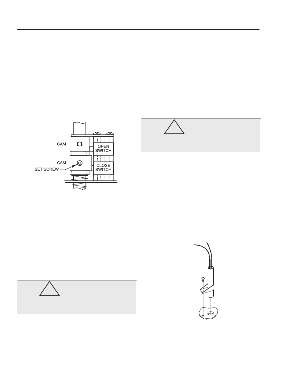
Each cam has two tapped holes with one setscrew that
may be placed at either location for easy access.
Cams are infinitely adjustable by using a 5/64” hex key.
Standard factory setting allows for 90 degrees reversible
rotation between open and close positions.
The bottom of the cam must be aligned with the bottom of
the travel limit switch button to allow the switch to function
properly during manual override.
Correct positioning of cam & switch are shown in the il-
lustration below, when in motor/automatic drive condition.
heater
To prevent condensation from forming inside the actuator,
Bray offers an optional heater. The heater is a PTC (Posi-
tive Temperature Coefficient) type, which has a unique
temperature - resistance characteristic. The heater self-
regulates by increasing its electrical resistance relative
to its temperature. The heater does not require external
thermostats or switches to control its heat output. It is
constructed of a polycrystalline ceramic, sandwiched
between two conductors, and wrapped inside a thermally
conductive electrical insulator.
Connect the heater wires to the terminal strip as indicated
on the wiring diagram.
WARNING
The heater surface can reach temperatures in excess
of 200 degrees Celsius.
h
eater
K
it
c
Onsists
Of
:
1. Heater with flying leads
2. Heater Mounting Bracket
3. #10 pan head screw, phillips drive
t
OOls
required
:
• For terminal wiring Screwdriver, 3/16” tip flat blade
• For heater mounting screw Screwdriver, No.1 phillips
i
nstallatiOn
PrOcedure
:
WARNING
Turn off all power and lock out service panel before
installing or modifying any electrical wiring.
The heater is mounted through a hole provided in the
switchplate.
1. Place the heater snugly into its mounting bracket
until approx.
1/2” is below the bracket as shown in
the illustration below.
2. Slip the heater into its mounting hole
3. Align the fastening hole in the bracket with the
threaded screw hole in the plate. Fasten the heater
to the switchplate.
4. Connect the heater wires to the terminal strip as
indicated on the wiring diagram.
BRAY Series 73 Electric Actuator
Operation and Maintenance Manual
8
!
!