GAI-Tronics XCP00600A Navigator Output Control Module Kit User Manual
Page 4
Pub. 43003-034B
Model XCP0600A Navigator Output Control Module Kit
Page: 4 of
6
\\s_eng\gtcproddocs\radio products-current release\43003\43003-034b\43003-034b.doc
09/08
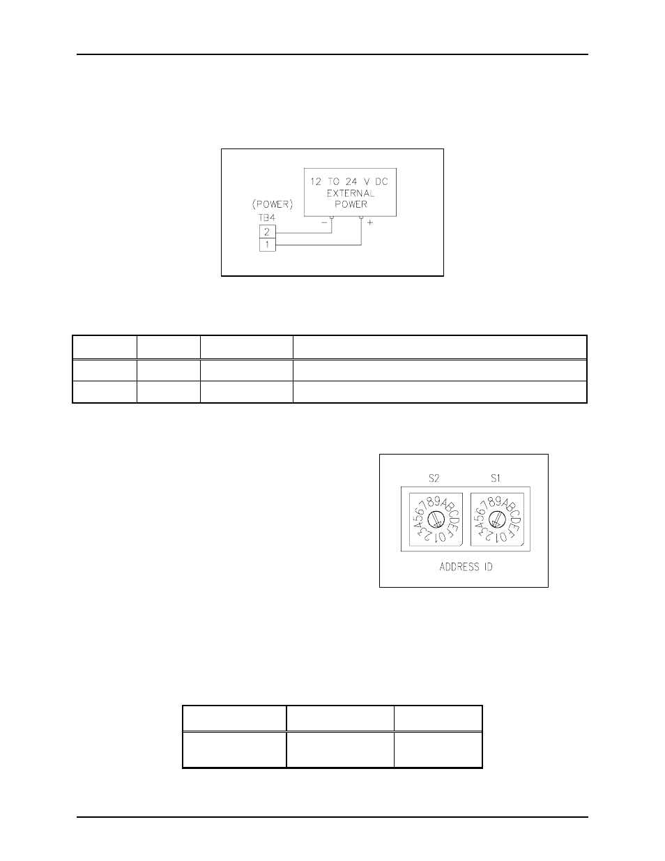
Power Connections
The Output Control Module requires a dc power supply. The dc power supply voltage must be between
12 and 24 V dc. TB4 is used for power connections. Please refer to the TB4 terminal block assignment
chart and Figure 3 below.
Figure 3. Power connections at TB4
Table 2.
Terminal Labeled Description Function
TB4-1
+
Power (+)
12 to 24 V dc power supply positive terminal
TB4-2
-
Power (-)
12 to 24 V dc power supply negative terminal
Address Switches S1 and S2
S1 and S2 are hexadecimal switches that are used
to set the I/O Controller’s address. If the system
contains more than one I/O Controller, each device
must be set with a different address. The device’s
address should be set in sequential order starting
with address 01. Switch S2 sets the first digit and
switch S1 sets the second digit. See Figure 4.
Example:
Address 01: S2 = 0, S1 = 1
Address 02: S2 = 0, S1 = 2
Address 03: S2 = 0, S1 = 3
N
OTE
: After changing the board address, the RESET button must be momentarily depressed for the new
address to take effect.
Table 3.
Hex Switch Settings
Hex Switch No.
Function
Settings
S1 and S2
Board address
S1 = 2
S2 = 0
Figure 4. Hex Switches S2 and S1